WASHERS/FRONT WIPER MOTOR -
INSTALLATION).
(2) Carefully position the wiper linkage module
and wiper motor to the underside of the cowl top
panel as a unit (Fig. 22).
(3) Install and tighten the two screws that secure
the wiper linkage module motor bracket to the flange
on the underside of the cowl top panel. Tighten the
screws to 6 N·m (50 in. lbs.).
(4) Install and tighten the nut and washer that
secures each wiper pivot housing to the outside of the
cowl top panel.
(5) Reconnect the wiper motor pigtail wire connec-
tor to the vehicle wire harness connector.
(6) Reinstall the ventilation housing onto the dash
panel and the underside of the cowl top panel (Fig.
21).
(7) Reinstall the wiper arms onto the wiper pivots.
(Refer to 8 - ELECTRICAL/WIPERS/WASHERS/
WIPER ARM - INSTALLATION).
(8) Reconnect the battery negative cable.
WIPER MOTOR
DESCRIPTION
The wiper motor is secured with three screws to a
motor bracket integral to the wiper linkage module
bracket located below the cowl top panel in the
engine compartment (Fig. 23). The wiper motor out-
put shaft passes through a hole in the motor bracket,
where a nut secures the wiper motor crank arm to
the motor output shaft. The two-speed permanent
magnet wiper motor features an integral transmis-
sion, an internal park switch, and an internal Posi-
tive Temperature Coefficient (PTC) circuit breaker.
The wiper motor cannot be adjusted or repaired. If
any component of the motor is faulty or damaged, the
entire wiper motor unit must be replaced.
OPERATION
The wiper motor operation is controlled by the
vehicle operator through battery current inputs
received by the wiper motor from the wiper switch
circuitry of the multi-function switch on the top of
the steering column, and from the wiper relay on the
fuse block underneath the steering column. The
wiper motor speed is controlled by current flow to
either the low speed or the high speed set of brushes.
The automatic resetting circuit breaker protects the
motor from overloads.
The park switch consists of a contact disc and
three contacts. The contact disc is mechanically fas-
tened to and rotated with a gear in the wiper motor
transmission. Two input contacts alternately close
the wiper park switch sense output circuit contact to
ground or to battery current, depending upon the
position of the wipers on the glass. This feature
allows the intermittent wipe logic circuit to monitor
the position and the cycles of the wiper motor to pro-
vide the intermittent wipe and wipe-after-wash
modes, as well as allowing the motor to complete its
current wipe cycle after the wiper system has been
turned Off and park the wiper blades in the lowest
portion of the wipe pattern.
The wiper motor may be diagnosed using conven-
tional diagnostic tools and methods.
REMOVAL
(1) Disconnect and isolate the battery negative
cable.
(2) Disconnect the vehicle wire harness connector
for the wiper motor from the motor pigtail wire con-
nector (Fig. 24).
(3) Remove the nut that secures the motor crank
arm to the wiper motor output shaft.
(4) If this wiper motor is to be reinstalled, make
an index mark between the wiper motor output shaft
and the motor crank arm using a suitable marker.
(5) Disengage the motor crank arm from the wiper
motor output shaft.
(6) Remove the three screws that secure the wiper
motor to the wiper linkage module motor bracket.
(7) Remove the wiper motor from the wiper link-
age module motor bracket.
INSTALLATION
(1) Position the wiper motor to the underside of
the wiper linkage module motor bracket (Fig. 24).
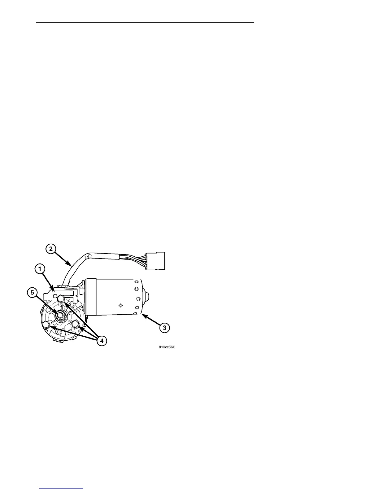
Fig. 23 Wiper Motor
1 - TRANSMISSION
2 - PIGTAIL WIRE
3 - MOTOR
4 - SCREW (3)
5 - OUTPUT SHAFT
VA WIPERS/WASHERS 8R - 19
WIPER LINKAGE (Continued)

 Loading...


