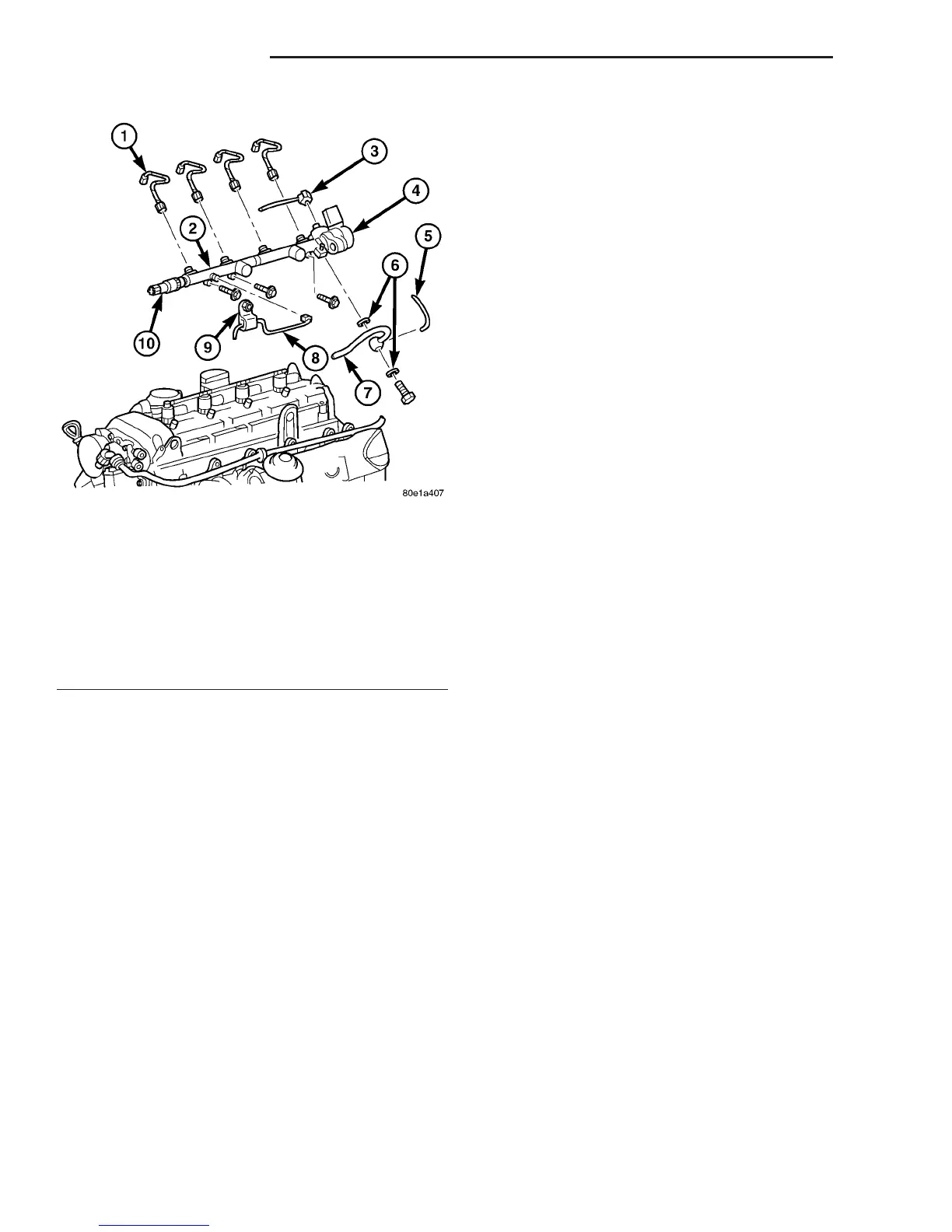
(1) Loosely position fuel rail into position on cylin-
der head.
(2) Position and loosely install fuel return line
from fuel filter, with new seals to rail (Fig. 7).
(3) Position fuel rail to cylinder head, feed in high
pressure line with new seals (Fig. 7).
CAUTION: Inspect sealing cones at the lines.
Replace as necessary. Ensure that all fuel pressure
lines are exactly located in original position.
(4) Hand start all injector lines (Fig. 7).
CAUTION: When tightening fuel injection line union
nuts, counter hold with a wrench at the thread con-
nection. ON NO ACCOUNT exceed the tightening
torque at any time.
(5) Tighten fuel rail bolts to 14 N·m (124 lbs.in.)
(Fig. 7).
(6) Tighten nut of pressure line to rail/injector to
22N·m (194 lbs.in.).
(7) Tighten nut of pressure line to high pressure
pump/rail to 22N·m (194 lbs.in.).
(8) Tighten banjo bolt of fuel return line to fuel
rail to 20N·m (177 lbs.in.).
(9) Install fuel temperature sensor.
(10) Install front engine support lift.
(11) Install thermostat housing.
(12) Reconnect engine harness electrical connec-
tors (Fig. 7).
(13) Refill cooling system.
(14) Connect negative battery cable.
WARNING: USE EXTREME CAUTION WHEN THE
ENGINE IS OPERATING. DO NOT STAND IN A
DIRECT LINE WITH FAN. DO NOT PUT YOUR
HANDS NEAR PULLEYS, BELTS OR FAN. DO NOT
WEAR LOOSE CLOTHING.
(15) Start engine and inspect for leaks (Refer to 14
- FUEL SYSTEM - WARNING).
FUEL TANK
DESCRIPTION
The plastic fuel tank is mounted to the frame rails
under the left/center side of the vehicle. The fuel
tank contains a serviceable fuel tank module (Fig. 8)
and fuel level sending unit. The tank is also
equipped with 2 fuel lines: a fuel supply line to the
fuel pump, and a separate fuel return line. A section
of the fuel return line is coiled (Fig. 8) at the rear
section of the tank. This coiled section is used to help
drop the temperature of fuel returning to the tank.
A fuel tank mounted, electric fuel pump is not used
with diesel powered models. Refer to Fuel Tank Mod-
ule for additional information.
REMOVAL
(1) Drain diesel fuel from tank using an approved
diesel fuel draining station.
(2) Disconnect fuel fill and vent lines (Fig. 8) from
body.
(3) Raise and support vehicle.
(4) Support tank with a hydraulic jack.
(5) Remove 2 fuel tank strap nuts and position
straps towards left side of vehicle.
(6) Carefully lower tank a few inches and discon-
nect electrical connector at top of fuel tank module.
(7) Disconnect fuel supply line at tank.
(8) Disconnect fuel return line at tank.
(9) Continue to carefully lower tank for removal.
(10) If fuel tank module is to be removed, thor-
oughly clean area at top of fuel tank around module.
(11) If fuel tank is to be replaced, remove fuel tank
module from tank. Refer to Fuel Tank Module
Removal/Installation procedures.
Fig. 7 FUEL PRESSURE SOLENOID
1 - INJECTION LINES
2 - FUEL RAIL
3 - FUEL RETURN LINE
4 - FUEL PRESSURE SOLENOID
5 - OIL LINE
6 - SEALS
7 - FUEL RETURN LINE AT COOLER
8 - HIGH PRESSURE FUEL LINE TO FUEL RAIL
9 - FUEL LINE BRACKET
10 - FUEL PRESSURE SENSOR
14 - 12 FUEL DELIVERY VA
FUEL RAIL (Continued)

 Loading...


