NOTE: In order to remove tension from the strut,
Raise the lower control arm approximately 10 mm
with a jack.
(2) Install the lower ball joint into the steering
knuckle. Tighten to 280 N·m (206 ft. lbs.).
(3) Install the strut bolts to the steering knuckle
(Fig. 8). Tighten to 185 N·m (136 ft. lbs.).
(4) Install the stop plate (Refer to 2 - SUSPEN-
SION/FRONT/SPRING STOP PLATES - INSTALLA-
TION).
(5) Lower the lower control arm.
(6) Attach the tie rod to the steering knuckle (Fig.
8). Tighten the nut to 130 N·m (96 ft. lbs.)
(7) Install the disc brake caliper adapter (Refer to
5 - BRAKES/HYDRAULIC/MECHANICAL/DISC
BRAKE CALIPER ADAPTER - INSTALLATION)
(Fig. 8).
(8) Install the front tire & wheel assembly (Refer
to 22 - TIRES/WHEELS/WHEELS - INSTALLA-
TION).
(9) Lower the vehicle.
(10) Remove the spring blocks between the spring
and the spring clamp plates, While the vehicles
wheels are on the ground.
(11) Roll the vehicle approximately 1 mm forwards
and the backwards, and rock firmly.
(12) Tighten the lower control arm nuts and bolts
to the frame to 150 N·m (110 ft. lbs.) (Fig. 8).
(13) Apply brake to actuate brake pressure.
SPRING
REMOVAL
(1) To do this next step the vehicle must be
on the ground. Remove the front and rear bolts on
the left and right spring clamp plates (Fig. 9).
(2) Raise and support the vehicle.
(3) Remove the front wheels.
(4) Remove the brake caliper adapter (Refer to 5 -
BRAKES/HYDRAULIC/MECHANICAL/DISC
BRAKE CALIPER ADAPTER - REMOVAL).Do not
allow the caliper to hang by the hose, support
the caliper accordingly.
(5) Remove the ABS sensor from the mounting
bore in the steering knuckle (Fig. 9).
(6) Remove the outer tie rod retaining nut and
separate the tie rod from the knuckle (Fig. 9) using
special tool C-3894–A.
NOTE: In order to remove tension from the strut,
Raise the lower control arm approximately 10 mm
with a jack.
(7) Remove the strut bolts from the steering
knuckle.
(8) Remove both stop plate bolts and rotate the
plates upwards with the stabilizer link attached.
(9) Lower the lower control arm.
(10) Remove the lower ball joint nut from the
steering knuckle.
(11) Separate the lower ball joint from the knuckle
using special tool 9282.
(12) Remove the lower control arm nuts and bolts
from the frame.
(13) Remove the lower control arm from the frame
(Fig. 9).
NOTE: To avoid damaging the transverse leaf
spring, cushion the pad on the jack accordingly.
(14) Support the transverse leaf spring in the cen-
ter with a jack.
(15) Remove the left and right spring clamp plates
(Refer to 2 - SUSPENSION/FRONT/SPRING CLAMP
PLATES - REMOVAL) (Fig. 9).
NOTE: The upper spring blocks between the engine
cradle and the spring are color coded, Make sure
not to mix the blocks per sides. The blocks are dif-
ferent in sizes to accommodate the weight of the
vehicle and driver in order for the vehicle to sit
level.
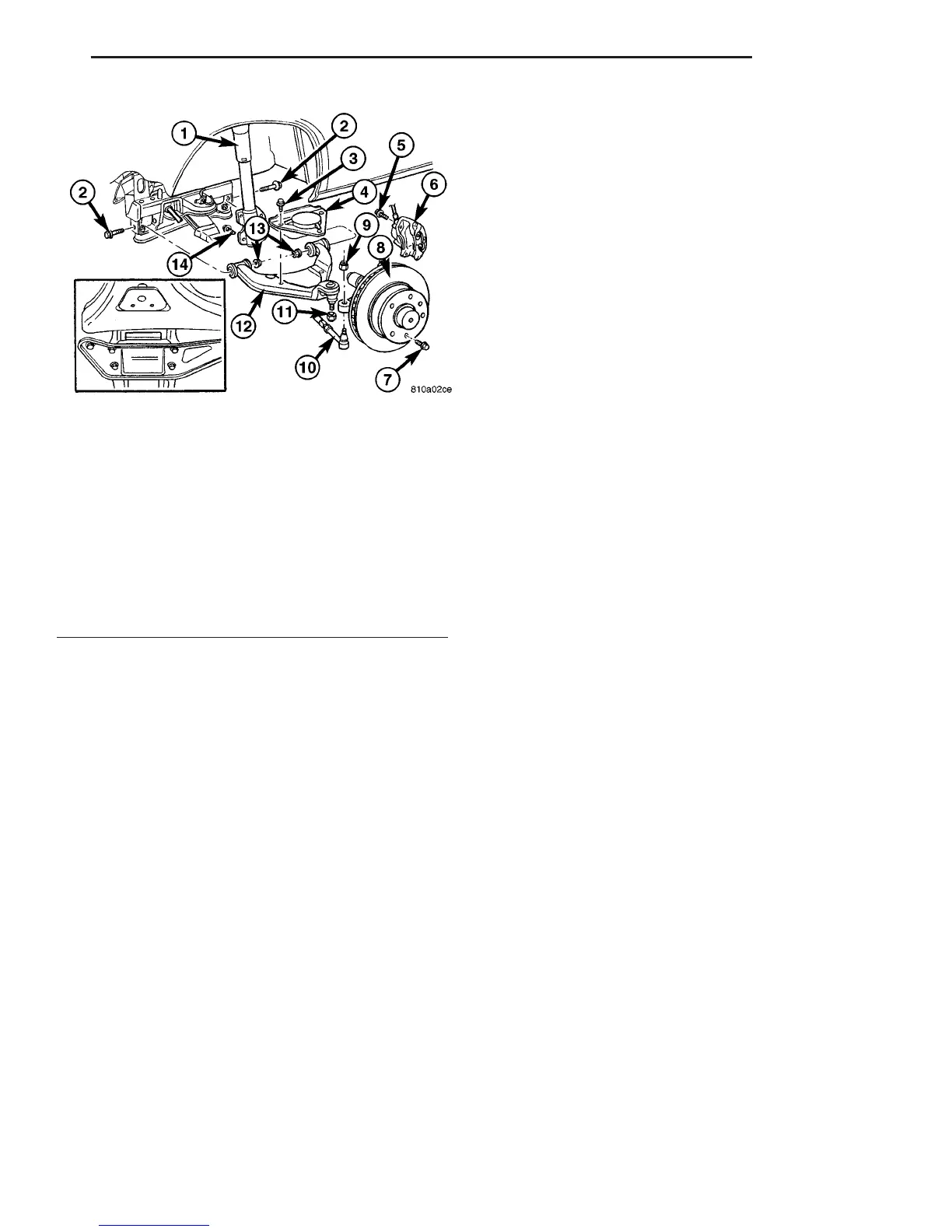
Fig. 8 LOWER CONTROL ARM
1 - STRUT
2 - LOWER CONTROL ARM BOLT
3 - STOP PLATE BOLT
4 - STOP PLATE
5 - CALIPER ADPTER BOLT
6 - DISC BRAKE CALIPER
7 - LOCKING BOLT
8 - DISC BRAKE ROTOR
9 - OUTER TIE ROD END RETAINING NUT
10 - OUTER TIE ROD END
11 - LOWER BALL JOINT NUT
12 - LOWER BALL JOINT
13 - LOWER CONTROL ARM NUTS
14 - STRUT BOLT
VA FRONT 2 - 7
LOWER CONTROL ARM (Continued)

 Loading...


