PROPELLER SHAFT
REMOVAL
(1) Secure vehicle to prevent it from rolling.
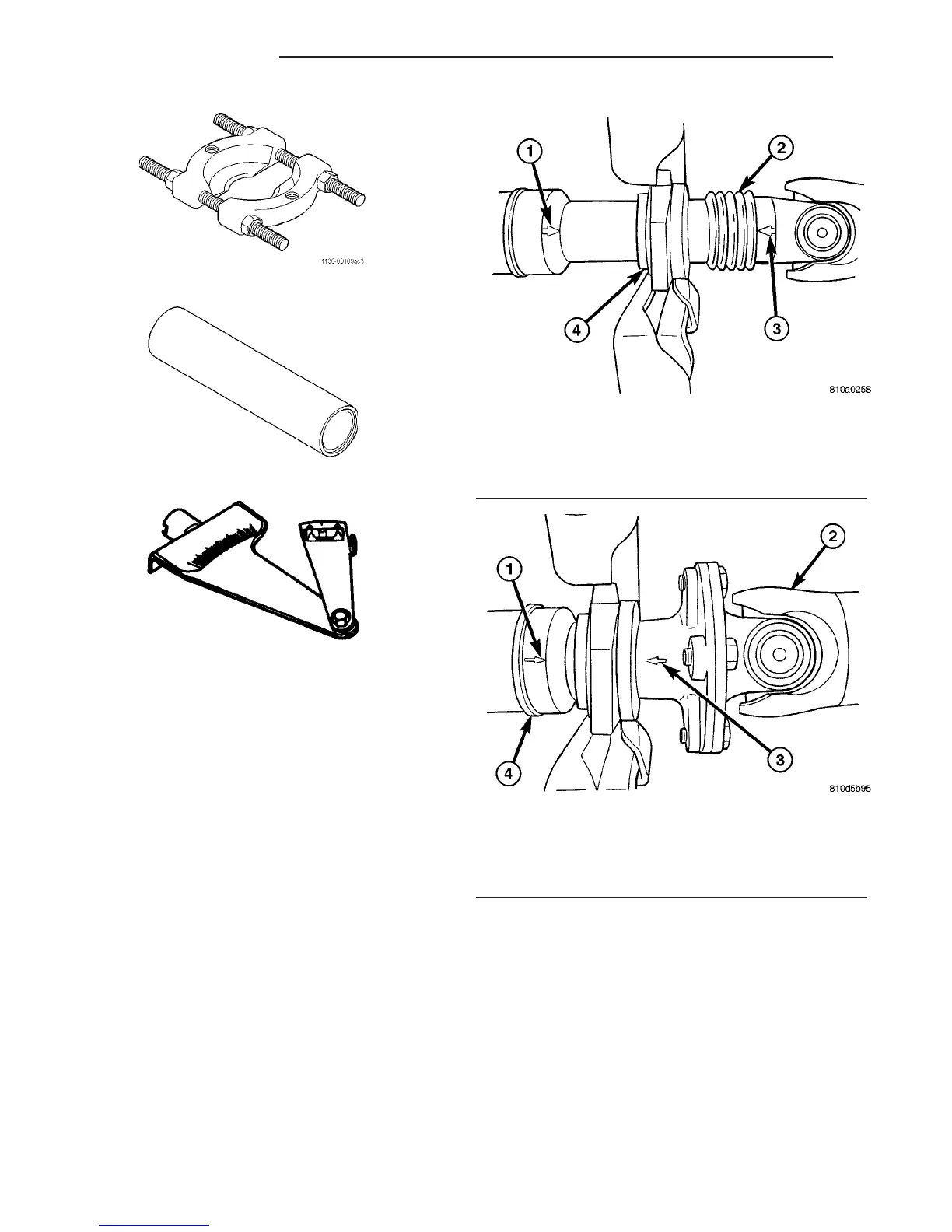
(2) Make installing reference marks on propeller
shaft (Fig. 6) and (Fig. 7).
(3) Remove retaining bracket bolts (Fig. 8) and
(Fig. 9).
(4) Remove propeller shaft bolts from rear axle
and transmission at the flange.
(5) Remove propeller shaft intermediate bearing
nuts from retaining bracket and bracket for brake
cable.
NOTE: The brake cable bracket is only installed in
vehicles with wheelbase 3550 mm
(6) Remove shaft from the vehicle.
INSTALLATION
(1) Install propeller shaft intermediate bearing/
bearings to support and tighten nuts to 105 N·m (77
ft. lbs.).
(2) Install propeller shaft intermediate bearing
support/supports to frame floor and tighten bolts to
95 N·m (70 ft. lbs.).
(3) Install propeller shaft intermediate bearing
with retaining bracket and bracket for brake cable.
NOTE: The bracket is only installed on vehicles
with wheelbase 3550 mm.
(4) Install propeller shaft to rear axle and trans-
mission flange with installation marks are aligned.
Tighten bolts to 70 N·m (66 ft. lbs.).
(5) Install retaining bracket and tighten bolts to
100 N·m (74 ft. lbs.).
SPLITTER 1130
INSTALLER 9275
INCLINOMETER 7663
Fig. 6 ALIGNMENT MARKS
1 - ALIGNMENT MARK
2 - BOOT
3 - ALIGNMENT MARK
4 - CENTER BEARING
Fig. 7 ALIGNMENT MARKS 3 PIECE SHAFT
1 - REFERNCE MARK
2 - CENTER SHAFT
3 - REFERENCE MARK
4 - REAR SHAFT
3 - 6 PROPELLER SHAFT VA
PROPELLER SHAFT (Continued)

 Loading...


