REMOVAL
(1) Disconnect and isolate the negative battery
cable.
(2) Remove the gear selector bezel trim. Refer to
the Body section for the procedure.
(3) Remove the storage bin. Refer to the Body sec-
tion for the procedure.
(4) Remove the switch bezel retaining screw and
remove the switch bezel from the instrument panel.
Refer to the Body section for the procedure.
(5) Disconnect electrical connections.
(6) Working from the underside of the switch, gen-
tly rock the switch back and forth out of its mounting
location in the switch bezel.
INSTALLATION
(1) Install the heated seat switch in its mounting
location in the switch bezel.
(2) Connect electrical connections.
(3) Position the switch bezel and install the retain-
ing screw. Refer to the Body section for the proce-
dure.
(4) Install the storage bin. Refer to the Body sec-
tion for the procedure.
(5) Install the gear selector bezel trim. Refer to the
Body section for the procedure.
(6) Connect the negative battery cable.
HEATED SEAT ELEMENT
DESCRIPTION
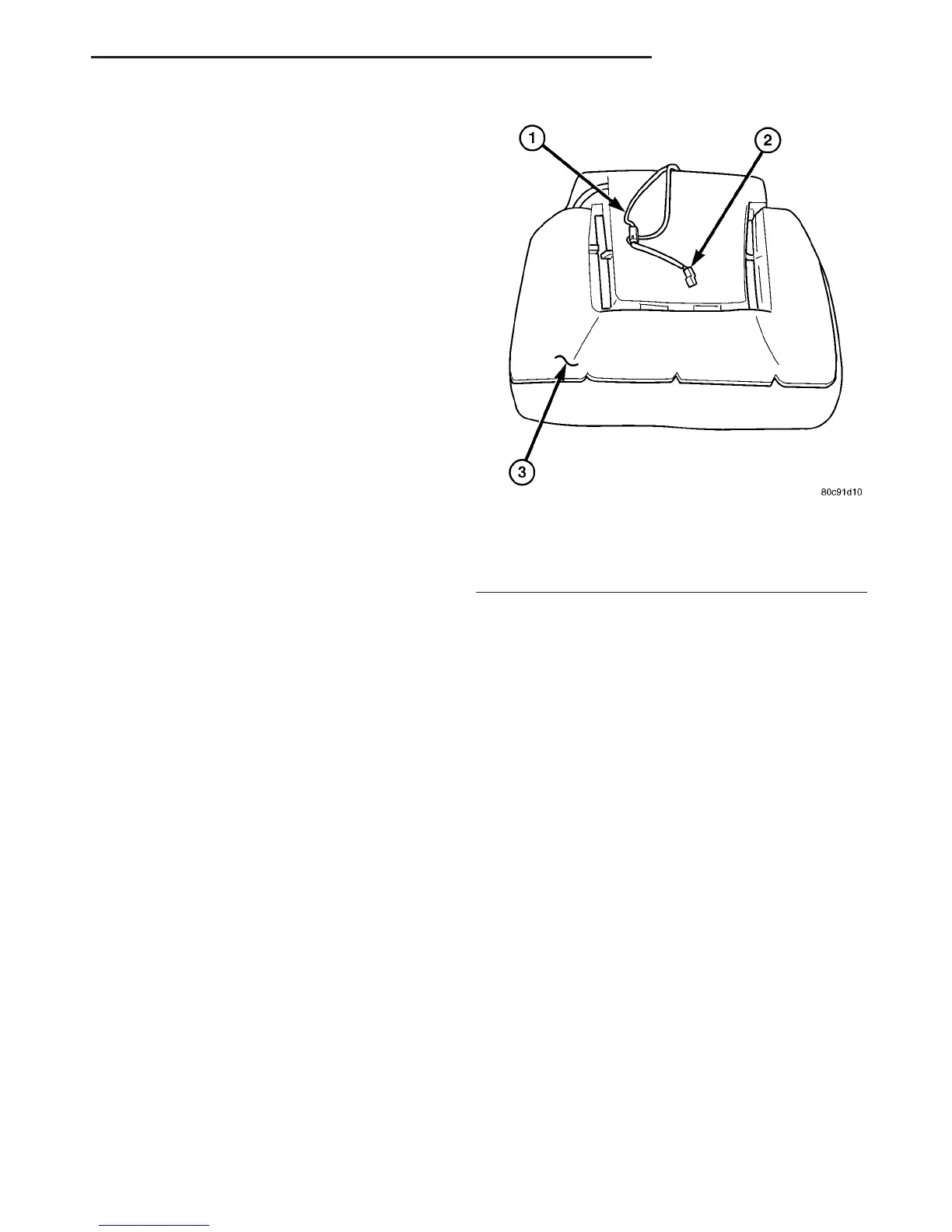
The heated seat system includes two seat heating
elements in each front seat, one for the seat cushion
(Fig. 1) and the other for the seat back. All models
use two resistor wire heating elements for each seat
that are connected in series with the Heated Seat
Relay. The temperature sensor is a Negative Temper-
ature Coefficient (NTC) thermistor. One temperature
sensor is used for each seat, and it is located in the
seat cushion heating element for all models.
The seat heating elements are glued onto the seat
and seat back cushions. The heated seat elements
and the temperature sensor cannot be adjusted or
repaired and, if faulty or damaged a new seat assem-
bly must be installed.
OPERATION
The heated seat elements resist the flow of electri-
cal current. When battery current is passed through
the elements, the energy lost by the resistance of the
elements is released in the form of heat. The heated
seat temperature sensor is a NTC thermistor. When
the temperature of the seat cushion cover rises, the
resistance of the sensor decreases. The heated seat
relay uses this temperature sensor input to monitor
the temperature of the seat, and regulates the cur-
rent flow to the seat heating elements accordingly.
DIAGNOSIS AND TESTING - HEATED SEAT
ELEMENT
For complete circuit diagrams, refer to Wiring.
NOTE: When checking heated seat elements for
continuity, be certain to move the heating element
being checked. Moving the element, such as sitting
in the seat will eliminate the possibility of an inter-
mittent open in the element which would only be
evident if the element was in a certain position.
Failure to check the element in various positions
could result in an incomplete test.
(1) Disconnect and isolate the battery negative
cable. Disconnect the heated seat element wire har-
ness connector from under the seat cushion. Check
for continuity between the seat heater driver circuit
and ground. There should be continuity, less than 7
ohms. If OK, go to Step 2. If not OK, replace the seat
assembly.
(2) Check for continuity between the seat heater
B+ driver circuit cavity and the seat back frame.
There should be no continuity. If OK, heating ele-
ment is OK at this time. If not OK, replace the seat
assembly.
Fig. 1 Heated Seat Element - Typical
1 - Seat Back Wire Harness
2 - Heated Seat Wire Harness Connector
3 - Heated Seat Cushion Element
VA HEATED SYSTEMS 8G - 3
DRIVER HEATED SEAT SWITCH (Continued)

 Loading...


