INSTALLATION
INSTALLATION - ENGINE COVER
(1) Align cover and install screws. tighten screws
to 11N·m (97 lbs. in.) (Fig. 2).
INSTALLATION
NOTE: Deburr and seal metal from cross plate
removal with anti corrosion material.
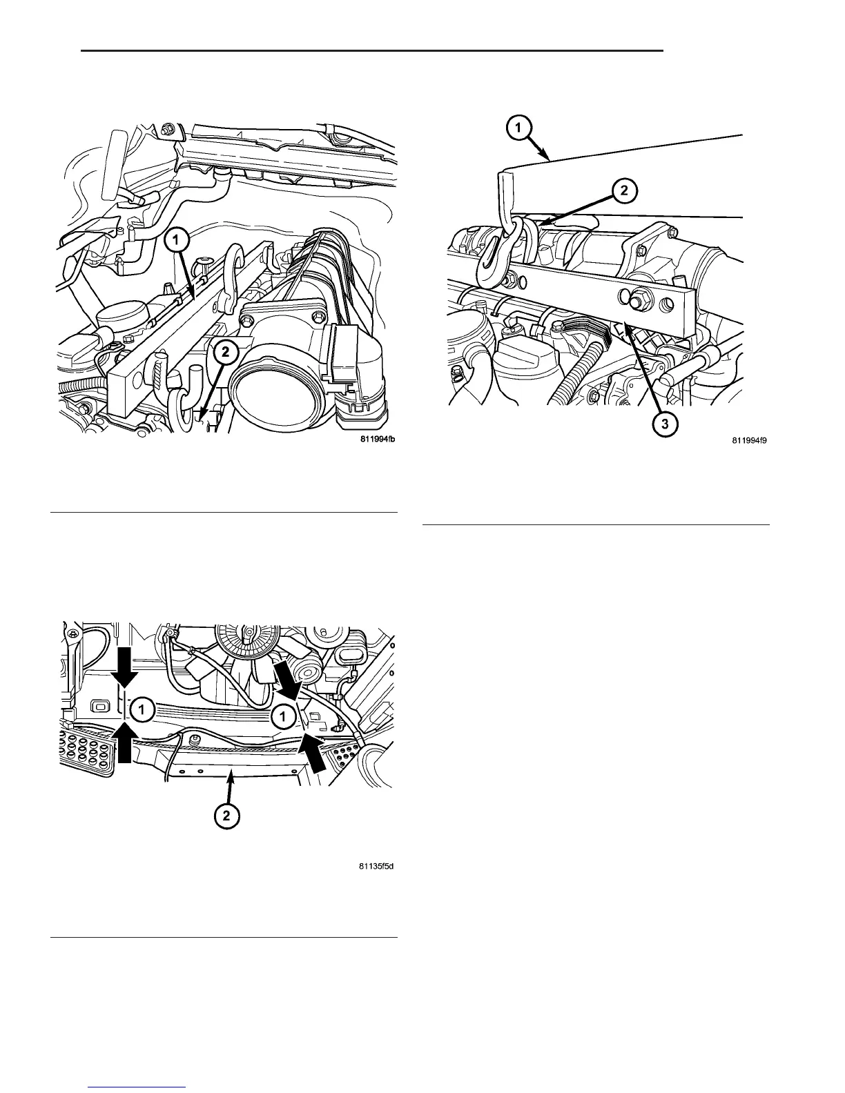
(1) Install the engine support fixture (Fig. 5).
(2) Install the engine lifting devise (Fig. 7).
(3) Install the engine assembly into the vehicle
engine compartment, mating the transmission and
the engine (Fig. 7).
(4) Lower the engine assembly until the engine
brackets align with the mounts.
(5) Hand start the engine mount bolts and remove
the engine lifting devise.
(6) Tighten the engine mount bolts to 83 N·m (62
lbs.ft.).
(7) Raise and support the vehicle.
(8) Install the transmission housing to engine
bolts. Refer to (Refer to 21 - TRANSMISSION/
TRANSAXLE/AUTOMATIC - NAG1 - INSTALLA-
TION) for correct sequence and torque specification.
(9) Install the torque converter bolts. Refer to
(Refer to 21 - TRANSMISSION/TRANSAXLE/AUTO-
MATIC - NAG1 - INSTALLATION) for correct
sequence and torque specification.
(10) Install the torque converter access plate.
Refer to (Refer to 21 - TRANSMISSION/TRANS-
AXLE/AUTOMATIC - NAG1 - INSTALLATION) for
correct sequence and torque specification.
Fig. 5 ENGINE LIFTING FIXTURE
1 - ENGINE LIFTING FIXTURE #9308
2 - ENGINE LIFTING EYES
Fig. 6 FRONT CROSS PLATE
1 - CUTTING POINT
2 - CORE SUPPORT
Fig. 7 ENGINE HOIST CONNECTION
1 - ENGINE HOIST
2 - CENTER EYELET OF ENGINE LIFTING FIXTURE
3 - ENGINE LIFTING FIXTURE #9308
VA ENGINE 9 - 7
ENGINE (Continued)

 Loading...


