TURN SIGNAL RELAY
REMOVAL
WARNING: ON VEHICLES EQUIPPED WITH AIRBAGS,
DISABLE THE SUPPLEMENTAL RESTRAINT SYSTEM
BEFORE ATTEMPTING ANY STEERING WHEEL,
STEERING COLUMN, DRIVER AIRBAG, PASSENGER
AIRBAG, SEAT BELT TENSIONER, OR INSTRUMENT
PANEL COMPONENT DIAGNOSIS OR SERVICE. DIS-
CONNECT AND ISOLATE THE BATTERY NEGATIVE
(GROUND) CABLE, THEN WAIT TWO MINUTES FOR
THE SYSTEM CAPACITOR TO DISCHARGE BEFORE
PERFORMING FURTHER DIAGNOSIS OR SERVICE.
THIS IS THE ONLY SURE WAY TO DISABLE THE SUP-
PLEMENTAL RESTRAINT SYSTEM. FAILURE TO TAKE
THE PROPER PRECAUTIONS COULD RESULT IN
ACCIDENTAL AIRBAG DEPLOYMENT AND POSSIBLE
PERSONAL INJURY.
(1) Disconnect and isolate the battery negative
cable.
(2) Remove the fuse access panel from the steering
column opening cover below the steering column on
the instrument panel.
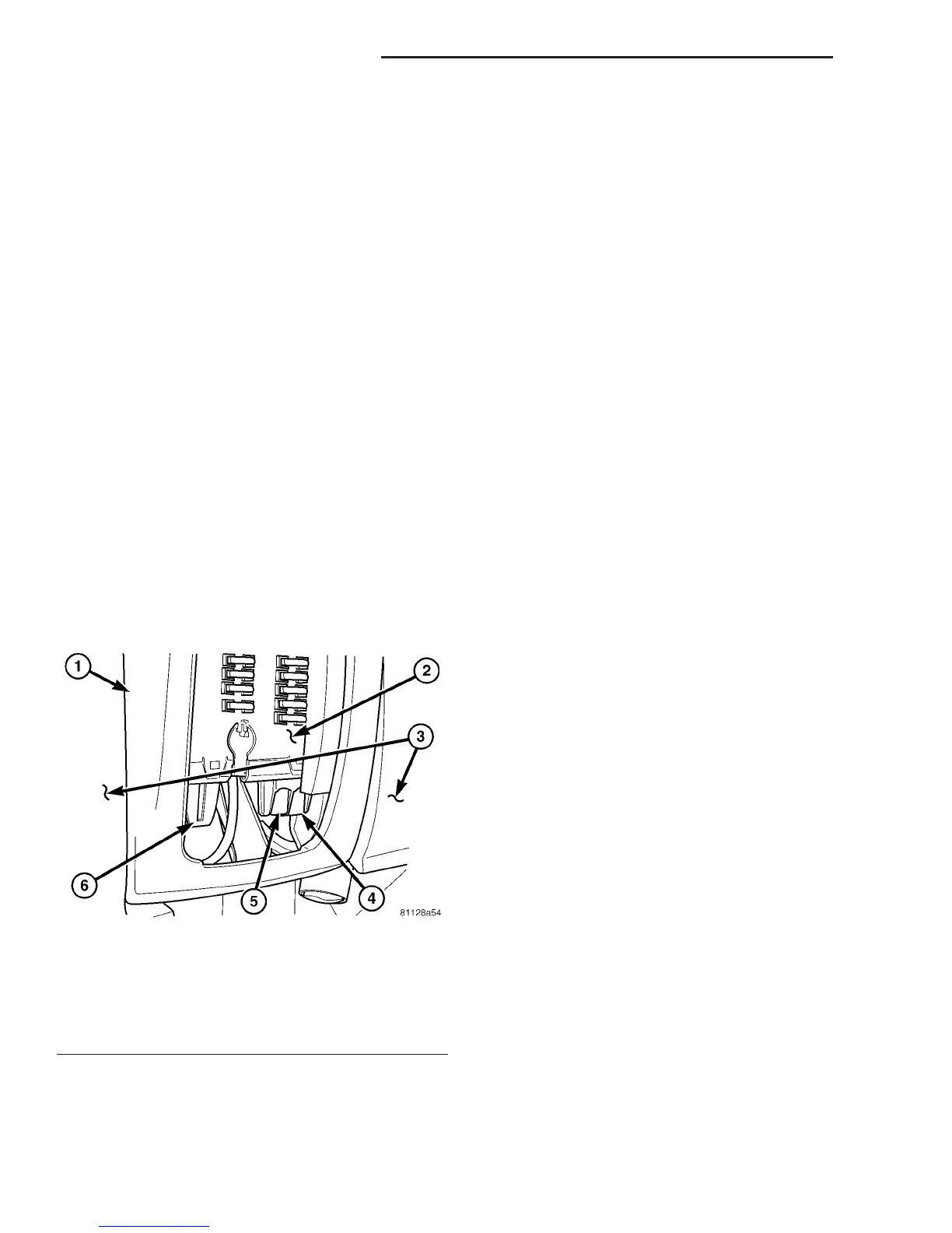
(3) Reach through and below the inboard side of
the fuse access opening to access the turn signal
relay (Fig. 47).
(4) Remove the turn signal relay by grasping it
firmly, releasing the latches and pulling it straight
down from the receptacle on the bottom of the fuse
block.
INSTALLATION
WARNING: ON VEHICLES EQUIPPED WITH AIR-
BAGS, DISABLE THE SUPPLEMENTAL RESTRAINT
SYSTEM BEFORE ATTEMPTING ANY STEERING
WHEEL, STEERING COLUMN, DRIVER AIRBAG,
PASSENGER AIRBAG, SEAT BELT TENSIONER, OR
INSTRUMENT PANEL COMPONENT DIAGNOSIS OR
SERVICE. DISCONNECT AND ISOLATE THE BAT-
TERY NEGATIVE (GROUND) CABLE, THEN WAIT
TWO MINUTES FOR THE SYSTEM CAPACITOR TO
DISCHARGE BEFORE PERFORMING FURTHER
DIAGNOSIS OR SERVICE. THIS IS THE ONLY SURE
WAY TO DISABLE THE SUPPLEMENTAL
RESTRAINT SYSTEM. FAILURE TO TAKE THE
PROPER PRECAUTIONS COULD RESULT IN ACCI-
DENTAL AIRBAG DEPLOYMENT AND POSSIBLE
PERSONAL INJURY.
(1) Position the turn signal relay to the receptacle
on the bottom of the fuse block (Fig. 47).
(2) Align the turn signal relay terminals with the
terminal cavities in the fuse block receptacle.
(3) Push firmly and evenly on the top of the turn
signal relay until the terminals are fully seated in
the terminal cavities in the receptacle of the fuse
block and both latches are fully engaged.
(4) Reinstall the fuse access panel onto the steer-
ing column opening cover below the steering column
on the instrument panel.
(5) Reconnect the battery negative cable.
Fig. 47 Turn Signal Relay
1 - STEERING COLUMN OPENING COVER
2 - FUSE BLOCK
3 - LOWER INSTRUMENT PANEL
4 - TURN SIGNAL RELAY
5 - ENGINE CONTROL MODULE RELAY
6 - WIPER RELAY
8L - 24 LAMPS/LIGHTING - EXTERIOR VA

 Loading...


