heard during a coast, the front pinion bearing is the
source.
Differential bearings usually produce a low pitch
noise. Differential bearing noise is similar to pinion
bearing noise. The pitch of differential bearing noise
is also constant and varies only with vehicle speed.
Axle shaft bearings produce noise and vibration
when worn or damaged. The noise generally changes
when the bearings are loaded. Road test the vehicle.
Turn the vehicle sharply to the left and to the right.
This will load the bearings and change the noise
level. Where axle bearing damage is slight, the noise
is usually not noticeable at speeds above 30 mph.
LOW SPEED KNOCK
Low speed knock is generally caused by a worn
U-joint or by worn side-gear thrust washers. A worn
pinion shaft bore will also cause low speed knock.
VIBRATION
Vibration at the rear of the vehicle is usually
caused by a:
• Damaged drive shaft.
• Missing drive shaft balance weight(s).
• Worn or out-of-balance wheels.
• Loose wheel lug nuts.
• Worn U-joint(s).
• Loose/broken springs.
• Damaged axle shaft bearing(s).
• Loose pinion gear nut.
• Excessive pinion yoke run out.
• Bent axle shaft(s).
Check for loose or damaged front-end components
or engine/transmission mounts. These components
can contribute to what appears to be a rearend vibra-
tion. Do not overlook engine accessories, brackets
and drive belts.
NOTE: All driveline components should be exam-
ined before starting any repair.
DRIVELINE SNAP
A snap or clunk noise when the vehicle is shifted
into gear (or the clutch engaged), can be caused by:
• High engine idle speed.
• Transmission shift operation.
• Loose engine/transmission/transfer case mounts.
• Worn U-joints.
• Loose spring mounts.
• Loose pinion gear nut and yoke.
• Excessive ring gear backlash.
• Excessive side gear to case clearance.
The source of a snap or a clunk noise can be deter-
mined with the assistance of a helper. Raise the vehi-
cle on a hoist with the wheels free to rotate. Instruct
the helper to shift the transmission into gear. Listen
for the noise, a mechanics stethoscope is helpful in
isolating the source of a noise.
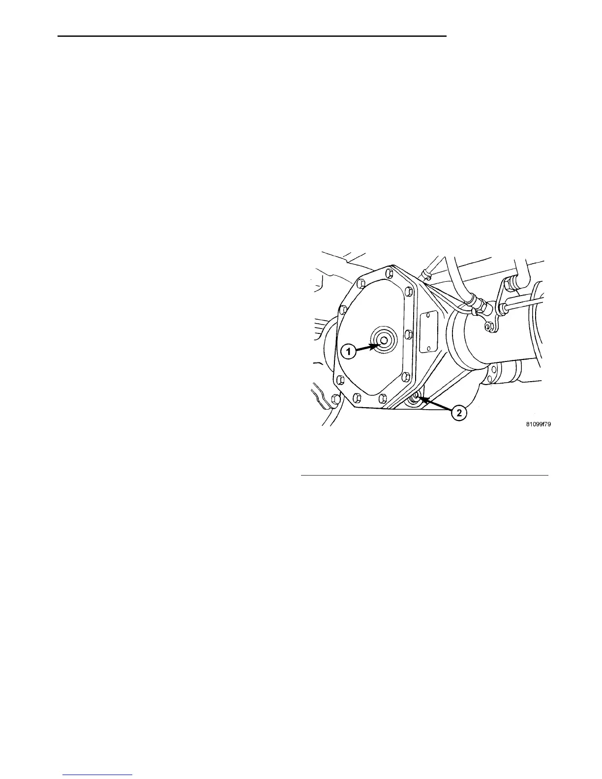
STANDARD PROCEDURE - DRAIN AND FILL
NOTE: Drain oil when warm.
(1) Clean area around oil fill plug and drain plug.
(2) Remove oil drain plug and drain oil (Fig. 1).
(3) Install oil drain plug and tighten to N·m 100
(74 ft. lbs.).
(4) Remove oil fill plug and fill housing up to bot-
tom edge of oil fill hole (Fig. 1).
(5) Install oil fill plug and tighten to N·m 100 (74
ft. lbs.).
REMOVAL
(1) Raise and support the vehicle.
(2) Position a suitable lifting device under the axle
and secure axle to device.
(3) Remove wheels and tires.
(4) Unplug wear indicator cable (Fig. 2) and (Fig.
3).
(5) Detach cable connector for brake pad wear
indicator.
(6) Remove ABS sensor and clamp bushing from
mounting bore.
NOTE: The right-hand ABS sensor cable is labeled
at the factory with a white tag.
(7) Remove cable ties from the park brake cables.
Release connection cable of brake pad wear indicator
and ABS sensor cable up to the relay unit of the
parking brake.
(8) Remove brake cables from adjuster.
(9) Remove brake calipers with adapters and lines.
Fig. 1 FILL PLUG
1 - FILL PLUG
2 - DRAIN PLUG
VA REAR AXLE 3 - 11
REAR AXLE (Continued)

 Loading...


