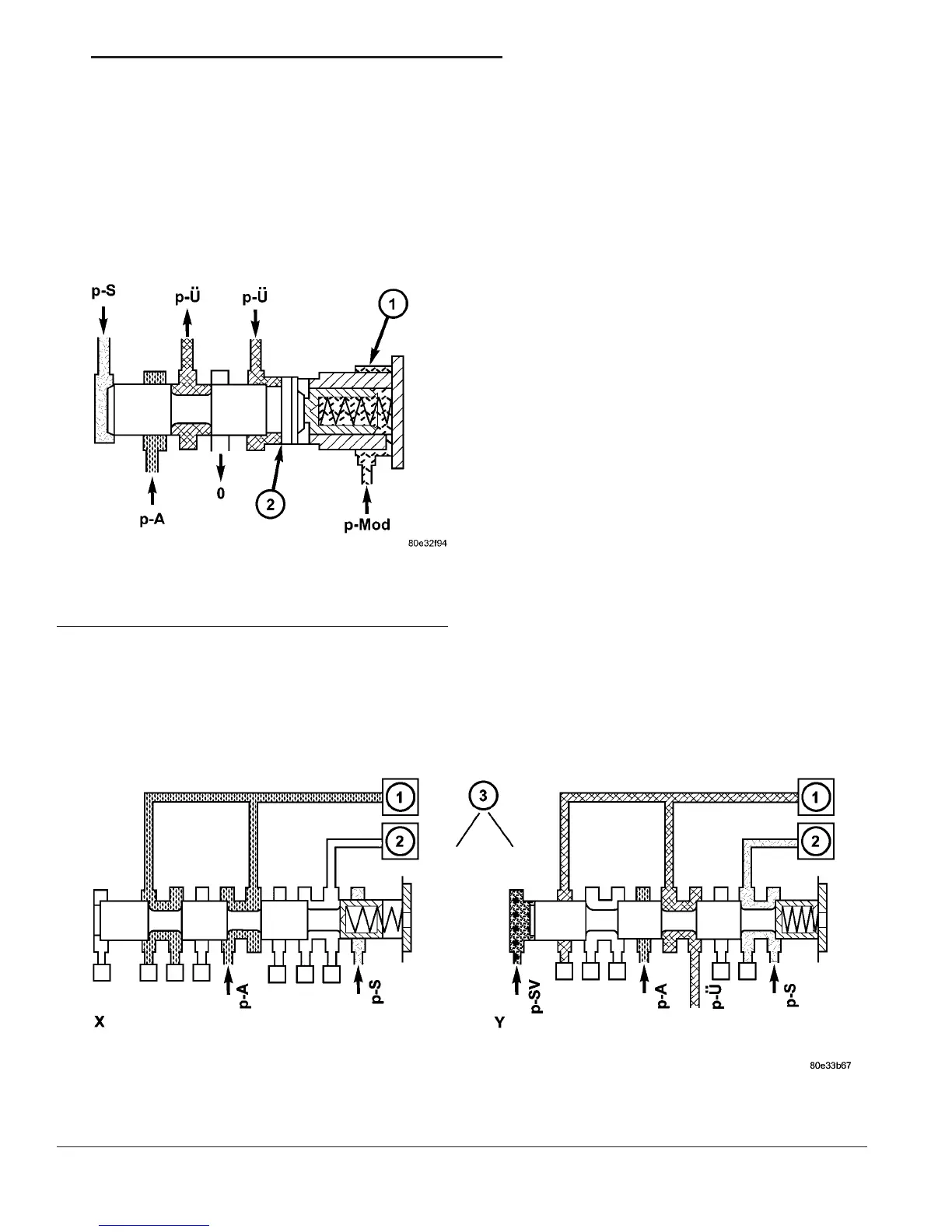
Overlap Regulating Valve
During the shift phase the pressure (Fig. 102) in
the deactivating shift actuator is regulated in rela-
tion to the engine load (modulating pressure) and the
pressure in the activating actuator. The regulated
pressure is inversely proportional to the transfer
capacity of the activating shift actuator (regulated
overlap).
Command Valve
When the end face is unpressurized (stationary
phase), the working pressure is directed to the actu-
ated shift element. If the end face of the command
valve (Fig. 103) is subjected to the shift valve pres-
sure (p-SV) (shift phase), then the shift pressure is
switched to the activating element and the overlap
pressure is switched to the deactivating element.
Shift Valve Holding Pressure
The holding pressure shift valve (Fig. 104) is actu-
ated by the pressures present at the end face in the
actuators and a spring. It assigns the working pres-
sure to the actuator with the higher pressure (taking
into account the spring force and the effective surface
area). The other element of the shift group is then
unpressurized. The valve switches over only during
the shift phase and only at a certain pressure ratio
between the overlap pressure (p-Ü) and the shift
pressure (p-S).
Shift Pressure Shift Valve
When the multiple-disc brake B1 (3) is activated,
the working pressure (pa) is applied to the end face
of the 1-2 / 4-5 shift pressure shift valve (4) (Fig. 105)
via the command valve (1). Its shift state is main-
tained during the shift phase by substituting the
shift element pressure acting on its end face (and
which is variable during the shift phase) with a cor-
responding constant pressure. When the multi-plate
clutch K1 (2) is activated, the end face of the shift
valve is unpressurized during the stationary and
shift phases, so the shift state is maintained during
the shift phase in this case too.
Fig. 103 Command Valve
1 - HOLDING CLUTCH B1
2 - DRIVING CLUTCH K1
3 - 1-2/4-5 COMMAND VALVE
Fig. 102 Overlap Regulating Valve
1 - OVERLAP REGULATING VALVE
2 - ANNULAR SURFACE ON OVERLAP REGULATING VALVE
VA AUTOMATIC TRANSMISSION - NAG1 21 - 89
ELECTROHYDRAULIC UNIT (Continued)

 Loading...


