Command Valve
Each shift group possesses one command valve
(Fig. 92). The 1-2 / 4-5 and 2-3 command valves are
installed in the shift valve housing; the 3-4 command
valve is installed in the valve housing. The command
valve switches the shift group from the stationary
phase to the shift phase and back again.
Holding Pressure Shift Valve
Each shift group possesses one holding pressure
shift valve (Fig. 93). The 1-2 / 4-5 and 2-3 holding
pressure shift valves are installed in the shift valve
housing; the 3-4 holding pressure shift valve is
installed in the valve housing. The holding pressure
shift valve allocates the working pressure to one
actuator of a shift group.
Fig. 89 Working Pressure Regulating Valve
1 - PRESSURE FROM K1/K2
2 - END FACE
3 - ANNULAR SURFACE
4 - WORKING PRESSURE REGULATING VALVE
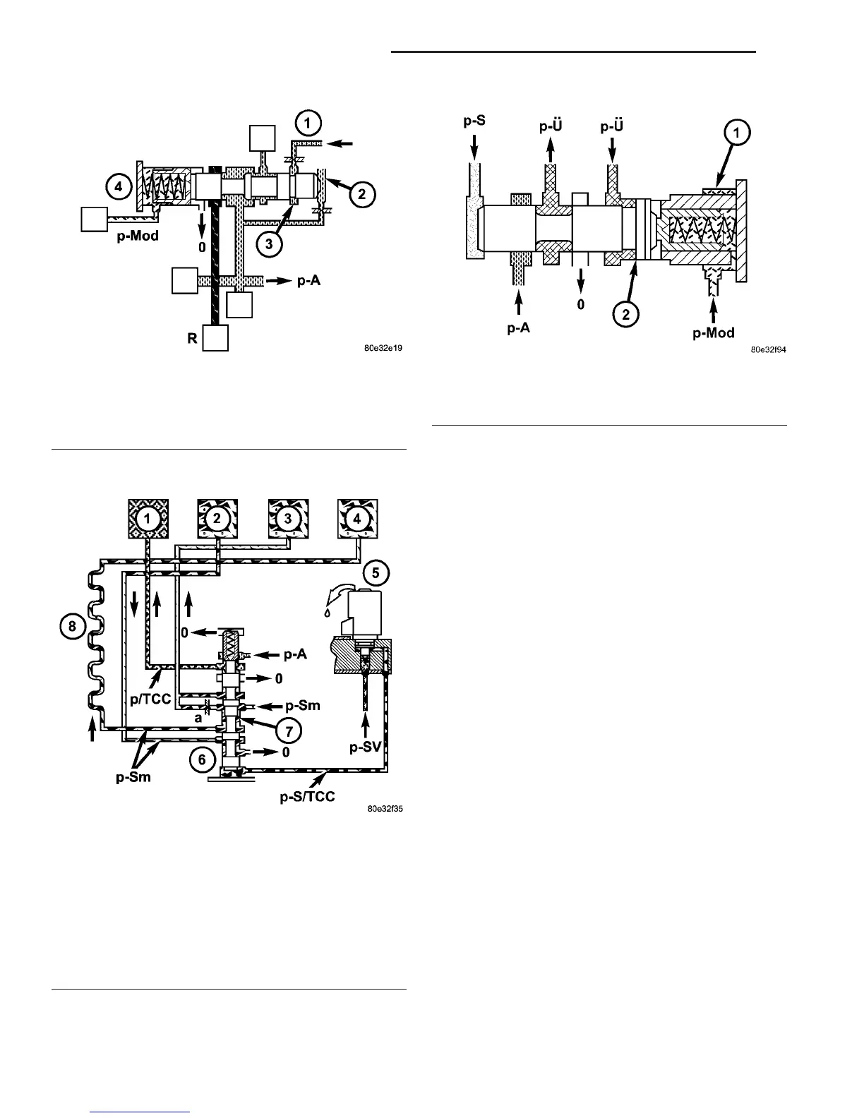
Fig. 90 Torque Converter Lockup Clutch Regulating
Valve
1 - TORQUE CONVERTER LOCK-UP CLUTCH
2 - TORQUE CONVERTER OUTPUT
3 - TORQUE CONVERTER INPUT
4 - TORQUE CONVERTER LUBRICATION POINTS
5 - TORQUE CONVERTER LOCK-UP SOLENOID
6 - TORQUE CONVERTER LOCK-UP CLUTCH REGULATING
VALVE
7 - ANNULAR PASSAGE THROTTLE
8 - OIL COOLER
Fig. 91 Overlap Regulating Valve
1 - OVERLAP REGULATING VALVE
2 - ANNULAR SURFACE ON OVERLAP REGULATING VALVE
21 - 84 AUTOMATIC TRANSMISSION - NAG1 VA
ELECTROHYDRAULIC UNIT (Continued)

 Loading...


