WARNING: USE EXTREME CAUTION WHEN THE
ENGINE IS OPERATING. DO NOT STAND IN A
DIRECT LINE WITH THE FAN. DO NOT PUT YOUR
HANDS NEAR THE PULLEYS, BELTS OR FAN. DO
NO WEAR LOOSE CLOTHING.
(11) Start the engine and inspect for leaks.
REMOVAL
(1) Disconnect negative battery cable.
(2) Remove engine cover.(Refer to 9 - ENGINE -
REMOVAL).
WARNING: (Refer to 14 - FUEL SYSTEM - WARN-
ING)
(3) Remove high pressure lines and injectors
(Refer to 14 - FUEL SYSTEM/FUEL INJECTION/
FUEL INJECTOR - REMOVAL).
(4) Remove cylinder head cover (Refer to 9 -
ENGINE/CYLINDER HEAD/CYLINDER HEAD
COVER(S) - REMOVAL).
NOTE: Rotate engine at the crankshaft only. DO
NOT rotate the engine at the camshaft. DO NOT
rotate the engine backward.
(5) Position piston of cylinder #1 to ignition TDC.
(6) Lock inlet camshaft (Fig. 19).
(7) Remove timing chain tensioner (Refer to 9 -
ENGINE/VALVE TIMING/TIMING BELT/CHAIN
AND SPROCKETS - REMOVAL).
NOTE: The lower portain of the cylinder head front
cover is sealed with RTV sealant. Carefully tug front
cover after bolt removal to loosen from cylinder
head.
(8) Remove cylinder head front cover (Refer to 9 -
ENGINE/CYLINDER HEAD - REMOVAL).
(9) Remove top side rail (Refer to 9 - ENGINE/
CYLINDER HEAD - REMOVAL).
CAUTION: For all work in which the crankshaft
should not rotate, secure camshaft gear to timing
chain.
(10) Mark camshaft sprocket relative to timing
chain.
(11) Unbolt camshaft sprocket from exhaust cam-
shaft.
NOTE: Note the position of dowel pin for camshaft
sprocket alignment during reassembly.
(12) Remove camshaft sprocket.
CAUTION: Camshaft bearing caps must remain in
proper order and position.
NOTE: Slacken the bolts of the camshaft bearing
caps evenly in steps of one turn until the backpres-
sure is eliminated. Camshafts must not be twisted
when slackening the camshaft bearing caps.
(13) Paint mark or scribe, then remove camshaft
bearing caps.
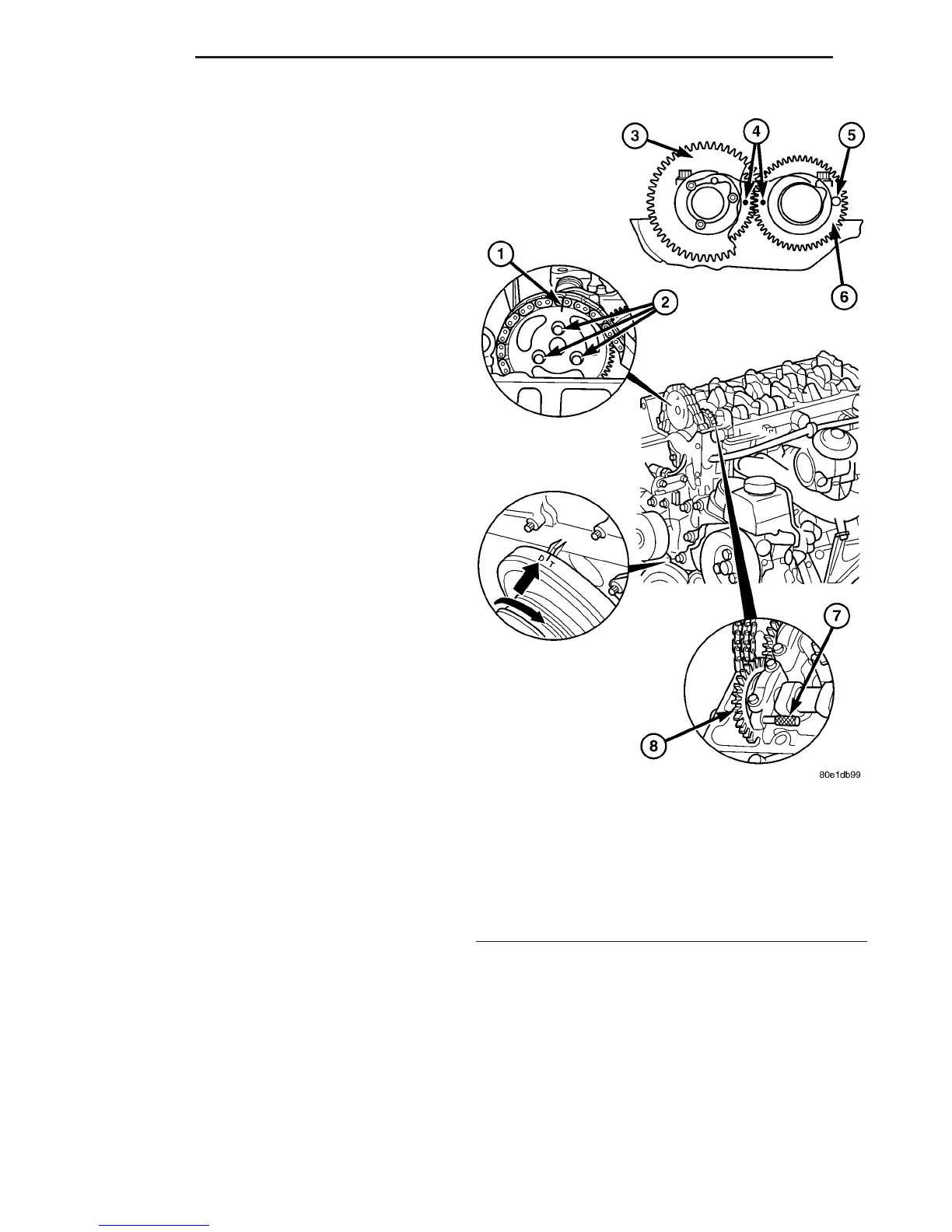
Fig. 19 CAMSHAFT ALIGNMENT
1 - EXHAUST CAMSHAFT SPROCKET AND CHAIN MARKING
2 - EXHAUST CAMSHAFT SPROCKET BOLTS
3 - EXHAUST CAMSHAFT SPROCKET
4 - CAMSHAFT ALIGNMENT DOTS
5 - INTAKE CAMSHAFT LOCK POSITION
6 - INTAKE CAMSHAFT SPROCKET
7 - INTAKE CAMSHAFT LOCK (SPECIAL TOOL #8929)
8 - INTAKE CAMSHAFT SPROCKET
9 - 28 ENGINE VA
CAMSHAFT(S) (Continued)

 Loading...


