voir on the right front fender wheel house in the
engine compartment. Only a molded plastic nipple
with a clear vent tube are visible near the top of the
washer pump/motor unit that is equipped with the
optional fluid level switch when it is installed in the
reservoir. The vent tube is routed to and retained in
an integral clip located behind the reservoir filler cap
near the top of the reservoir. This version of the
washer pump/motor unit also has a third terminal
pin in its integral connector receptacle. The washer
fluid level switch cannot be adjusted or repaired. If
faulty or damaged, the entire washer pump/motor
unit must be replaced.
OPERATION
The washer fluid level switch monitors the level of
the washer fluid in the washer reservoir. When the
fluid level in the washer reservoir is at or above the
predetermined minimum, the switch contacts are
open. When the fluid level in the washer reservoir
falls below the predetermined minimum, the switch
contacts of the normally open switch close. The
washer fluid level switch is connected to the vehicle
electrical system through the washer pump/motor
unit take out and connector of the vehicle wire har-
ness. The switch receives a path to ground at all
times through another take out of the vehicle wire
harness with a single eyelet terminal connector that
is secured under a ground screw located near the
right headlamp in the engine compartment.
The switch is connected in series between ground
and the washer fluid switch sense input to the Elec-
troMechanical Instrument Cluster (EMIC). When the
switch closes, the EMIC senses the ground on the
washer fluid switch sense circuit. The EMIC is pro-
grammed to respond to this input by illuminating the
washer fluid indicator. The washer fluid level switch
input to the EMIC may be diagnosed using conven-
tional diagnostic tools and methods.
WASHER HOSES/TUBES
DESCRIPTION
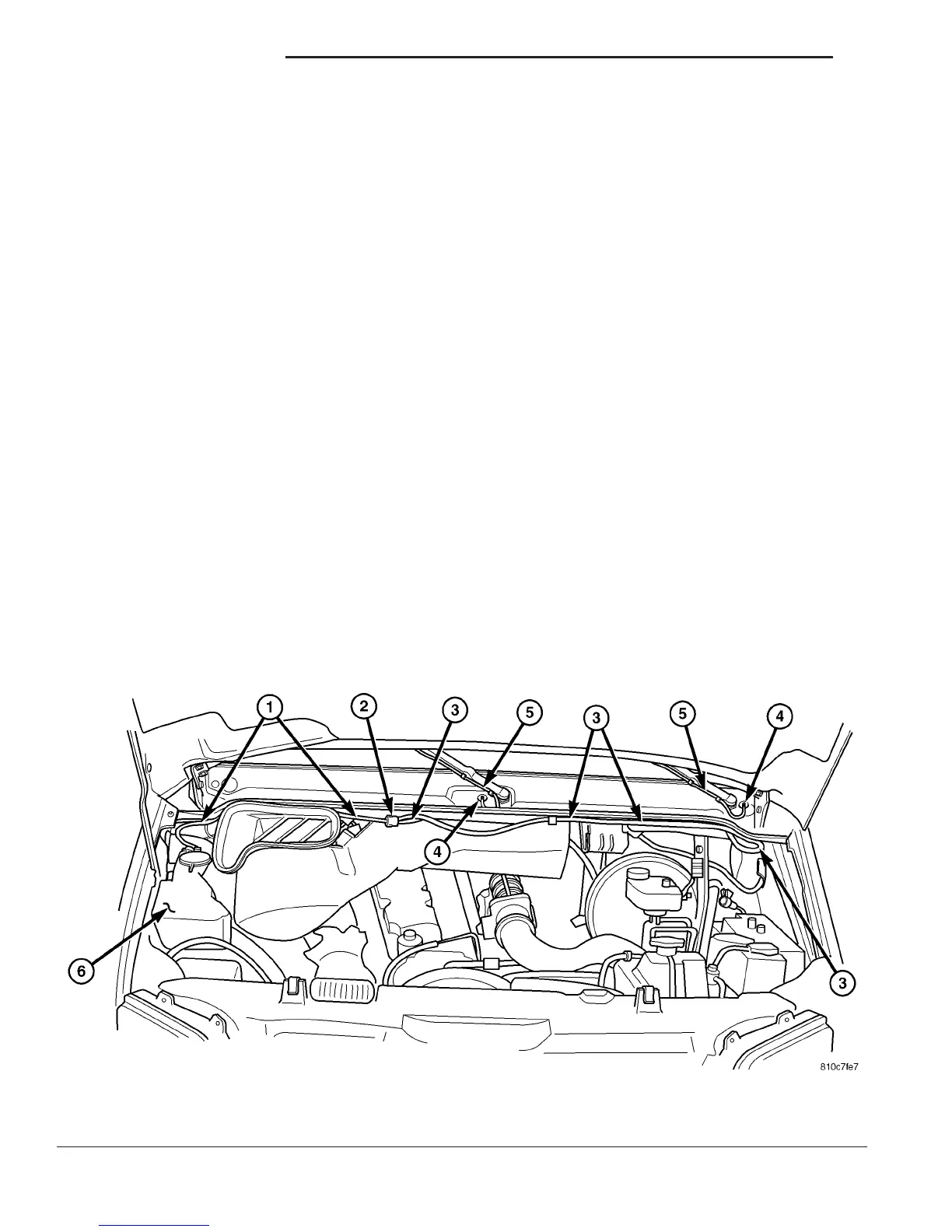
The washer plumbing consists of a small diameter
rubber hose that is routed from the barbed outlet
nipple of the washer pump/motor on the washer res-
ervoir to the check valve just below the cowl top
panel behind the rear of the hood opening in the
engine compartment (Fig. 6). The other two barbed
nipples of the check valve are connected to two short
lengths of hose that each terminate at a molded plas-
tic elbow that passes through a rubber grommet from
the engine compartment to the outside of the cowl
top panel near each wiper pivot. The two washer noz-
zle hoses are then connected from the elbow fittings
on the outside of the cowl top panel along the under-
side of the wiper arms to the two washer nozzles.
Washer hose is available for service only as roll stock,
which must then be cut to length. The molded plastic
Fig. 6 Washer Plumbing
1 - WASHER SUPPLY HOSE 4 - ELBOW FITTING (2)
2 - CHECK VALVE 5 - WIPER ARM WASHER HOSE (2)
3 - WASHER NOZZLE HOSE (2) 6 - WASHER RESERVOIR
8R - 8 WIPERS/WASHERS VA
WASHER FLUID LEVEL SWITCH (Continued)

 Loading...


