(5) Adjust the parking park.
(6) Lower the vehicle.
INSTALLATION - REAR
NOTE: Route the park brake cable free of tension
and the risk of chafing.
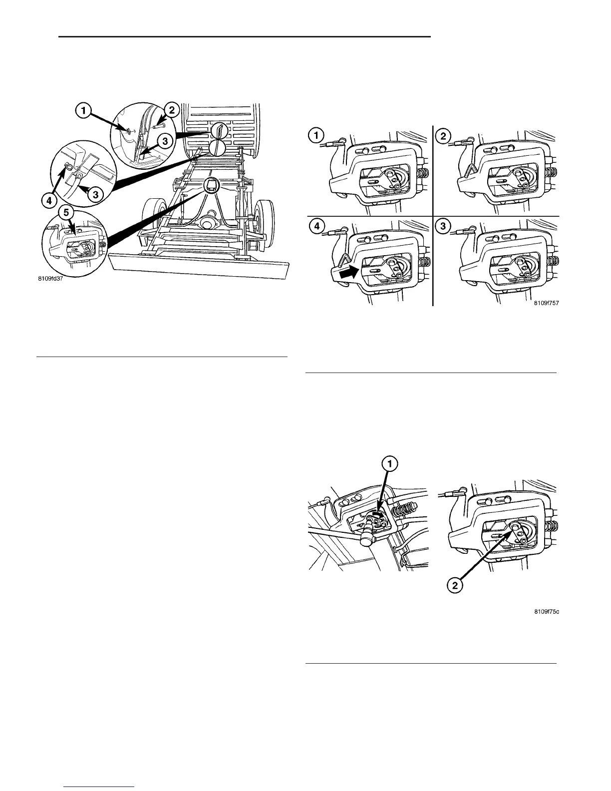
(1) Install the hand brake cable to the anchor
plate (Fig. 31).
(2) Install the park brake cable lock (Fig. 31).
(3) Install all connections on the hardware cable
(Fig. 31).
(4) Install the park brake cables to the shoe (Fig.
31).
(5) Install the park brake shoes.
(6) Install the rear wheels.
(7) Adjust the park brakes.
(8) Lower the vehicle.
ADJUSTMENTS
ADJUSTMENT - PARKING BRAKE CABLES
(1) Loosen the bolts of the mounting brackets (Fig.
33).
(2) Insert a drill bit or an allen wrench with a 6
mm diameter between the mounting bracket and
front lever (Fig. 33).
(3) Push the mounting bracket back until the front
brake cable is free of play and without tension (Fig.
33).
(4) Tighten the bolts to the mounting bracket
Tighten to 25 N·m (221 in. lbs.) (Fig. 33).
(5) Remove the 6 mm diameter drill bit or allen
wrench (Fig. 33).
(6) Tighten the hand brake lever one notch (Fig.
33).
(7) Clamp the eccentric clockwise until the wheels/
disc brake rotors can still be turned with the force of
the hand (Fig. 34).
(8) Tighten the clamp bolt (Fig. 34).
(9) Release the hand brake lever.
(10) Check the wheel for free movement.
Fig. 32 FRONT PARK BRAKE CABLE
1 - RETAINING CLIP
2 - LOCKING PIN
3 - FRONT PARK BRAKE CABLE
4 - RETAINING CLIP
5 - PARK BRAKE CABLE ADJUSTER
Fig. 33 PARK BRAKE ADJUSTER
1 - LOOSEN MOUNTING BOLTS
2-6mmALLEN WRENCH
3 - MOUNTING BOLTS TIGHTENED
4 - FREEPLAY WITH NO TENSION
Fig. 34 PARK BRAKE ADJUSTMENT
1 - ECCENTRIC CLOCKWISE
2 - CLAMP SCREW TIGHTENED
VA BRAKES - BASE 5 - 25
CABLES (Continued)

 Loading...


