INSTALLATION
(1) Insert the removed terminal in the same cavity
on the repair connector.
(2) Repeat steps for each terminal in the connec-
tor, being sure that all wires are inserted into the
proper cavities. For additional connector pin-out
identification, refer to the wiring diagrams.
(3) When the connector is re-assembled, the sec-
ondary terminal lock must be placed in the locked
position to prevent terminal push out.
(4) Replace dress cover (if applicable).
(5) Connect connector to its mating half/compo-
nent.
(6) Connect battery and test all affected systems.
DIODE
REMOVAL
(1) Disconnect the battery.
(2) Locate the diode in the harness, and remove
the protective covering.
(3) Remove the diode from the harness, pay atten-
tion to the current flow direction (Fig. 10).
INSTALLATION
(1) Remove the insulation from the wires in the
harness. Only remove enough insulation to solder in
the new diode.
(2) Install the new diode in the harness, making
sure current flow is correct. If necessary, refer to the
appropriate wiring diagram for current flow.
(3) Solder the connection together using rosin core
type solder only. Do not use acid core solder.
(4) Tape the diode to the harness using electrical
tape. Make sure the diode is completely sealed from
the elements.
(5) Re-connect the battery and test affected sys-
tems.
TERMINAL
REMOVAL
(1) Follow steps for removing terminals described
in the connector removal section.
(2) Cut the wire 6 inches from the back of the con-
nector.
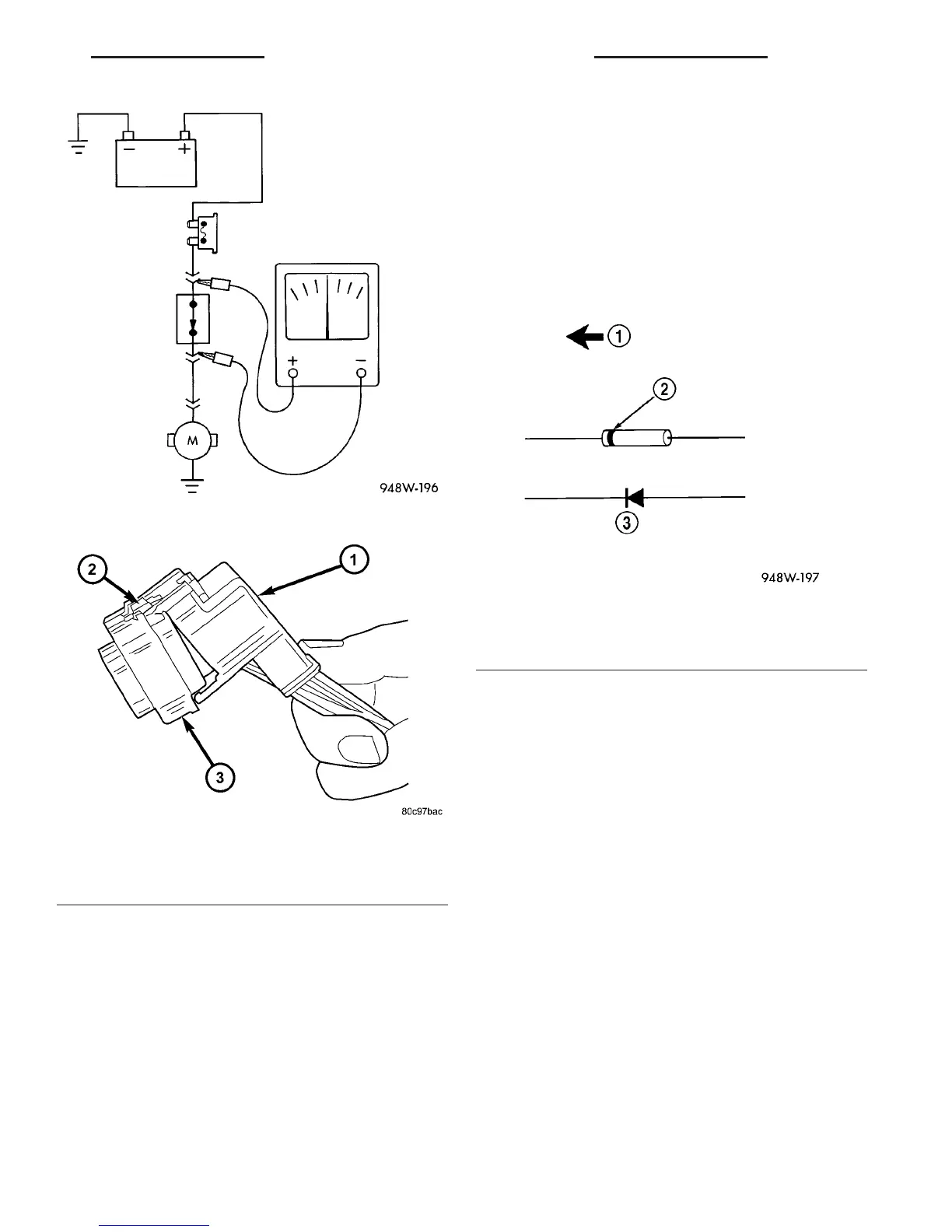
Fig. 8 Testing for Voltage Drop
Fig. 9 REMOVAL OF DRESS COVER
1 - DRESS COVER
2 - CONNECTOR LOCK
3 - CONNECTOR
Fig. 10 Diode Identification
1 - CURRENT FLOW
2 - BAND AROUND DIODE INDICATES CURRENT FLOW
3 - DIODE AS SHOWN IN THE DIAGRAMS
VA 8W-01 WIRING DIAGRAM INFORMATION 8W - 01 - 9
CONNECTOR (Continued)

 Loading...


