WIPER LINKAGE
DESCRIPTION
The wiper linkage and pivots are concealed within
the engine compartment below the cowl top panel
(Fig. 20). The ends of the wiper pivot shafts that pro-
trude through dedicated openings in the cowl top
panel to drive the wiper arms and blades are the
only visible components of the wiper linkage module.
The wiper linkage module consists of the following
major components:
• Linkage - The two wiper drive links are each
constructed of stamped steel. The left (driver) side
drive link has a plastic socket-type bushing in one
end, and a plastic sleeve-type bushing in the other
end. The socket bushing is snap-fit over the ball stud
on the left pivot crank arm, while the sleeve bushing
is fit over the longer ball stud on the wiper motor
crank arm. The right (passenger) side drive link has
a plastic socket-type bushing on each end. One end of
this drive link is snap-fit over the exposed end of the
longer ball stud on the wiper motor crank arm and
captures the sleeve bushing end of the left drive link
beneath it, while the other end is snap-fit over the
ball stud on the right pivot crank arm.
• Module Bracket - The linkage module bracket
consists of a long tubular steel main member that is
crimped to a molded plastic pivot bracket at each end
where the wiper pivots are secured. A stamped steel
mounting plate for the wiper motor is secured with
welds near the center of the main member and is
then secured with screws to the underside of the cowl
top panel.
• Motor Crank Arm - The wiper motor crank
arm is a stamped steel unit with a round hole on the
driven end that is secured to the wiper motor output
shaft with a nut, and a long ball stud secured to the
drive end.
• Pivot - The two molded plastic wiper pivot
brackets are secured to the ends of the linkage mod-
ule bracket tubular member. The crank arms that
extend from the bottom of the pivot shafts each have
a ball stud on their end. The upper end of each pivot
shaft where the wiper arms will be fastened each is
tapered and externally serrated with a threaded stud
at the top where the wiper arms are secured by a
nut. Each pivot shaft operates within a housing
formed in the pivot bracket featuring a large external
flange near its center and external threads near the
top. The pivot housings are secured to the outer sur-
face of the cowl top panel by a large washer and a
nut threaded onto the outside of the housing where it
protrudes through the cowl top.
The wiper linkage module cannot be adjusted or
repaired. If any component of the linkage module is
faulty or damaged, the entire wiper linkage module
unit must be replaced.
OPERATION
The wiper linkage operation is controlled by the
output of the wiper motor through the wiper motor
crank arm. The wiper motor crank arm, the two
wiper drive links, and the two wiper pivots mechan-
ically convert the rotary output of the wiper motor to
the back and forth wiping motion of the wiper arms
and blades on the glass.
REMOVAL
(1) Disconnect and isolate the battery negative
cable.
(2) Remove the wiper arms from the wiper pivots.
(Refer to 8 - ELECTRICAL/WIPERS/WASHERS/
WIPER ARM - REMOVAL).
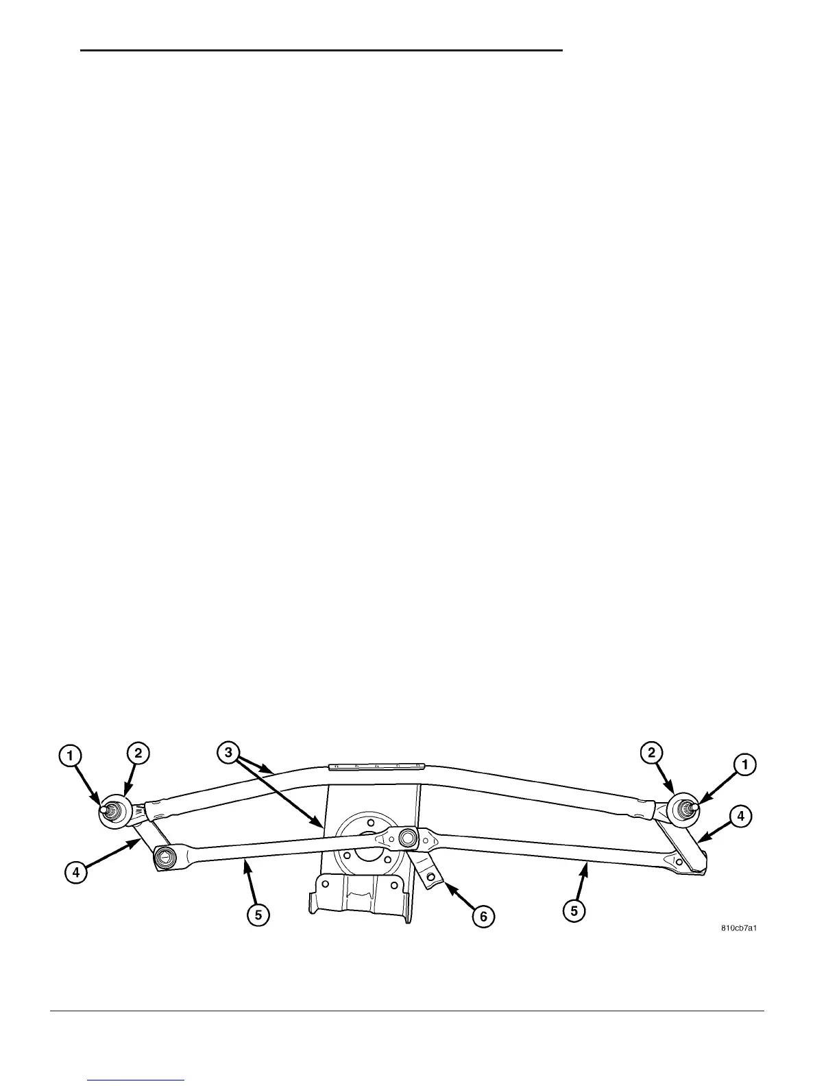
Fig. 20 Wiper Linkage Module
1 - PIVOT SHAFT (2) 4 - PIVOT CRANK ARM (2)
2 - PIVOT SHAFT HOUSING (2) 5 - DRIVE LINK (2)
3 - MODULE BRACKET 6 - MOTOR CRANK ARM
VA WIPERS/WASHERS 8R - 17

 Loading...


