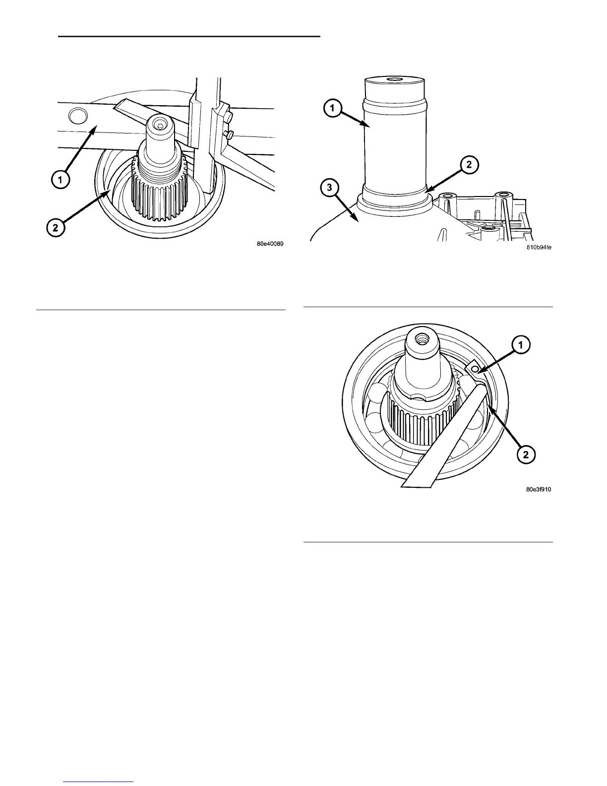
(a) Using Bearing Installer 9287 (Fig. 50),
install the output shaft bearing into the transmis-
sion housing. The closed side of the plastic
cage must point towards the parking lock
gear.
(b) Install the retaining ring (Fig. 51). Ensure
that the retaining ring is seated correctly in the
groove.
(c) Check that there is no play between the bear-
ing and the retaining ring using feeler gauge.
(d) There must be no play between the retaining
ring and the bearing. If the ring cannot be
installed, a thinner ring must be used. If there is
play between the ring and the bearing, a thicker
ring must be installed. Retaining rings are avail-
able in thicknesses of 2.0 mm (0.079 in.), 2.1 mm
(0.083 in.), and 2.2 mm (0.087 in.).
(24) Rotate the transmission so that the bellhous-
ing is pointed upward and ensuring that the output
shaft is allowed to move freely.
(25) Measure input shaft end-play (Fig. 52).
NOTE: If end-play is incorrect, transmission is
incorrectly assembled, or the geartrain end-play
shim is incorrect. The geartrain end-play shim is
selective.
(a) Attach Adapter 8266-18 to Handle 8266-8.
(b) Attach dial indicator C-3339 to Handle
8266-8.
(c) Install the assembled tool onto the input
shaft of the transmission and tighten the retaining
screw on Adapter 8266-18 to secure it to the input
shaft.
(d) Position the dial indicator plunger against a
flat spot on the oil pump and zero the dial indica-
tor.
(e) Move input shaft in and out and record read-
ing. End play should be 0.3-0.5 mm (0.012-0.020
in.). Adjust as necessary.
Fig. 49 Measure From Transmission Housing To
Rear Bearing Contact Surface
1 - GAUGE BAR 6311
2 - OUTPUT SHAFT BEARING CONTACT SURFACE
Fig. 50 Install Output Shaft Bearing
1 - BEARING INSTALLER 9287
2 - BEARING
3 - TRANSMISSION CASE
Fig. 51 Install Rear Output Shaft Retaining Ring
1 - RETAINING RING
2 - OUTPUT SHAFT BEARING
VA AUTOMATIC TRANSMISSION - NAG1 21 - 39
AUTOMATIC TRANSMISSION - NAG1 (Continued)

 Loading...


