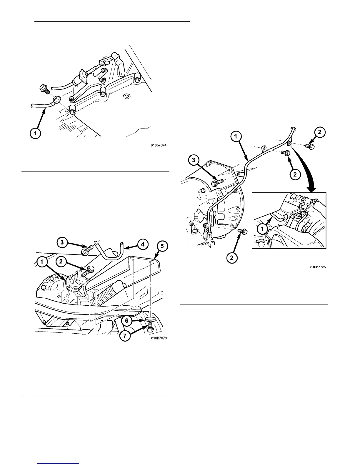
(17) Install exhaust heat shield (5) (Fig. 70).
(18) Install retaining bracket (4) (Fig. 70). Bracket
is asymmetric. The slanted side must be installed on
the left side in the direction of travel.
(19) Attach propeller shaft (1) (Fig. 70) to the
transmission (Refer to 3 - DIFFERENTIAL & DRIV-
ELINE/PROPELLER SHAFT/PROPELLER SHAFT -
INSTALLATION).
(20) Install oil filler pipe.
(a) Guide oil filler pipe (1) (Fig. 71) down and
into position.
(b) Push lower connection of oil filler pipe (1)
(Fig. 71) into the fill hole in the side of the trans-
mission housing.
(c) Install bolts (2) (Fig. 71) to cylinder head.
Tighten the bolts to 8 N·m (71 in.lbs.).
(d) Install bolt (3) (Fig. 71) to transmission
flange and bolt (2) to transmission housing.
Tighten the bolt to 8 N·m (71 in.lbs.).
Fig. 69 Install Driver’s Side Cooler Line
1 - COOLER LINE
Fig. 70 Install Propeller Shaft and Heat Shield
1 - PROPELLER SHAFT
2 - BOLT
3 - BOLT
4 - RETAINING BRACKET
5 - HEAT SHIELD
6 - WASHER
7 - BOLT
Fig. 71 Install the Fill Tube
1 - FILL TUBE
2 - BOLTS TO CYLINDER HEAD AND TRANSMISSION HOUSING
3 - BOLT TO TRANSMISSION FLANGE
VA AUTOMATIC TRANSMISSION - NAG1 21 - 45
AUTOMATIC TRANSMISSION - NAG1 (Continued)

 Loading...


