COLUMN
TABLE OF CONTENTS
page page
COLUMN
SPECIFICATIONS - TORQUE CHART .........5
INTERMEDIATE SHAFT
REMOVAL .............................5
INSTALLATION ..........................5
KEY/LOCK CYLINDER
REMOVAL .............................6
INSTALLATION ..........................7
STEERING WHEEL
REMOVAL .............................7
INSTALLATION ..........................7
COLUMN
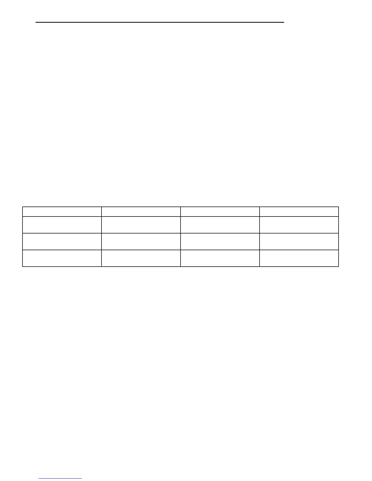
SPECIFICATIONS - TORQUE CHART
TORQUE SPECIFICATIONS
DESCRIPTION N·m Ft. Lbs. In. Lbs.
Steering Wheel With
Airbag To Steering Shaft
80 59 —
Jacket Tube For Steering
Shaft To Waist Rail
25 18 221
U-Joint To Steering Gear
Shaft
24 18 212
INTERMEDIATE SHAFT
REMOVAL
(1) Disconnect the ground cable from the battery.
(2) Remove the air bag module from the steering
wheel.
(3) Turn the steering wheel and lock the steering
wheel in the straight ahead position. The position
of the steering gear must not be altered again
for the entire duration of the work procedure.
(4) Remove the electrical center.
(5) Remove the steering wheel bolt.
(6) Remove the steering wheel from the steering
column.
(7) Remove the clockspring. Unscrew the retain-
ing bolts just enough to be able to remove the
clockspring. Do not twist or disassemble the
clockspring.
(8) Remove the combination switch.
(9) Disconnect the electrical connector for the igni-
tion lock.
(10) Remove the spring for the brake pedal from
the steering column.
(11) Remove the fitted bolt from the universal joint
(Fig. 1).
(12) Remove the bolts in the steering column
bracket (Fig. 2).
(13) Remove the steering shaft with the universal
joint off the steering gear drive shaft (Fig. 1).
(14) Pull the steering shaft out of the rubber grom-
met in the cab floor.
INSTALLATION
(1) Install the steering shaft through the rubber
grommet in the cab floor. Ensure that the rubber
grommet is properly seated.
(2) Install the steering shaft with the universal
joint onto the steering gear shaft (Fig. 1).
(3) Install the bolts in the steering column bracket
(Fig. 2). Tighten to 24 N·m (18 ft. lbs.).
(4) Install the universal joint on the steering gear
shaft (Fig. 1). Tighten to 24 N·m (18 ft. lbs.).
VA COLUMN 19 - 5

 Loading...


