(2) Counter hold the camshaft with an open end
wrench and install driver of inlet camshaft sprocket.
Tight bolt to 50N·m (37 lbs. ft.).
(3) Remove camshaft sprocket locking pin.
(4) Carefully raise locking pawl of top guide rail
and install front cover at cylinder head.
(5) Install timing chain tensioner with new gasket
(Refer to 9 - ENGINE/VALVE TIMING/TIMING
BELT/CHAIN AND SPROCKETS - INSTALLA-
TION).
(6) Install engine cover (Refer to 9 - ENGINE/
CYLINDER HEAD/CYLINDER HEAD COVER(S) -
INSTALLATION).
(7) Reconnect negative battery cable.
WARNING: US EXTREME CAUTION WHEN THE
ENGINE IS OPERATING. DO NOT STAND IN A
DIRECT LINE WITH THE FAN. DO NOT PUT YOUR
HANDS NEAR THE PULLEYS, BELTS OR FAN. DO
NOT WEAR LOOSE CLOTHES.
(8) Start engine and inspect for leaks.
CAMSHAFT(S)
STANDARD PROCEDURE - CHECKING
CAMSHAFT POSITION
(1) Disconnect negative battery cable.
(2) Remove engine cover (Refer to 9 - ENGINE
COVER - REMOVAL).
WARNING: (Refer to 14 - FUEL SYSTEM - WARN-
ING)
(3) Remove injectors (Refer to 14 - FUEL SYS-
TEM/FUEL INJECTION/FUEL INJECTOR -
REMOVAL).
(4) Clean injectors and recesses(Refer to 14 -
FUEL SYSTEM/FUEL INJECTION/FUEL INJEC-
TOR - STANDARD PROCEDURE).
(5) Remove cylinder head cover (Refer to 9 -
ENGINE/CYLINDER HEAD/CYLINDER HEAD
COVER(S) - REMOVAL).
NOTE: Rotate engine at crankshaft only. DO NOT
crank engine at the camshaft and DO NOT rotate
the engine backward.
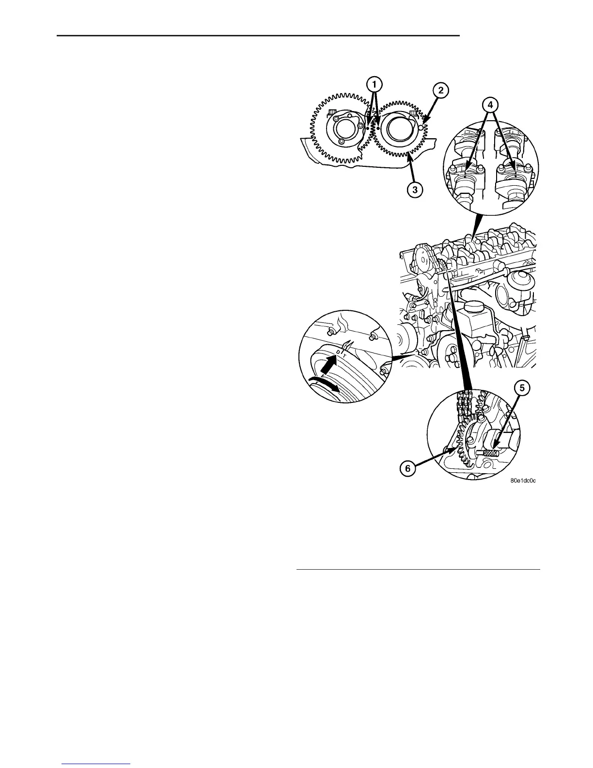
(6) Position piston of cylinder #1 to ignition TDC.
(7) Insert the locking pin (special tool #8929)
through first camshaft bearing cap into the hole in
the left inlet camshaft sprocket (Fig. 18).
NOTE: The two markings in the inlet camshaft
sprockets must be positioned opposite and mark-
ings of camshaft and camshaft bearing cap must be
aligned. If not, perform basic position of camshafts.
(8) Remove locking pin from camshaft bearing cap
hole.
(9) Install cylinder head cover (Refer to 9 -
ENGINE/CYLINDER HEAD/CYLINDER HEAD
COVER(S) - INSTALLATION).
(10) Install injectors (Refer to 14 - FUEL SYS-
TEM/FUEL INJECTION/FUEL INJECTOR -
INSTALLATION).
Fig. 18 CHECKING CAMSHAFT POSITION
1 - CAMSHAFT SPROCKET ALIGNMENT DOTS
2 - CAMSHAFT LOCK POSITION
3 - INTAKE CAMSHAFT SPROCKET
4 - CAMSHAFT AND BEARING CAP ALIGNMENT MARKS
5 - CAMSHAFT LOCKING PIN (SPECIAL TOOL #8929)
6 - INTAKE CAMSHAFT SPROCKET
VA ENGINE 9 - 27
CYLINDER HEAD (Continued)

 Loading...


