Injector opens fully
The control plunger reaches its upper stop where it
remains supported by a cushion of fuel which is gen-
erated by the flow of fuel between the bleed and feed
orifices. The injector nozzle has now opened fully,
and the fuel is injected into the combustion chamber
at a pressure almost equal to that in the fuel rail
(Fig. 8).
Injector closes (end of injection)
As soon as the solenoid valve is no longer trig-
gered, the valve spring forces the armature down-
wards and the ball closes the bleed orifice. The
armature is a 2–piece design. Here, although the
armature plate is guided by a driver shoulder in its
downward movement, it can “overspring” with the
return spring so that it exerts no downwards-acting
forces on the armature and the ball. The closing of
the bleed orifice lead to pressure build up in the con-
trol chamber via the input from the feed orifice. This
pressure is the same as that in the rail and exerts an
increased force on the control plunger through its
end face. This force, together with that of the spring,
now exceeds the force exerted by the chamber volume
and the nozzle needle closes. Injection ceases as soon
as the nozzle needle comes up against its bottom stop
again (Fig. 8).
STANDARD PROCEDURE
STANDARD PROCEDURE - INJECTOR
CLASSIFICATION
The classification of injectors into 3 classes
describes the quantity characteristic of the injector.
This will make it possible in the future to match the
engine software to the tolerances of the injector
within a more narrowly graduated range. Classifica-
tion can be clearly recognized, and assigned only by
means of a DRBIIIt.
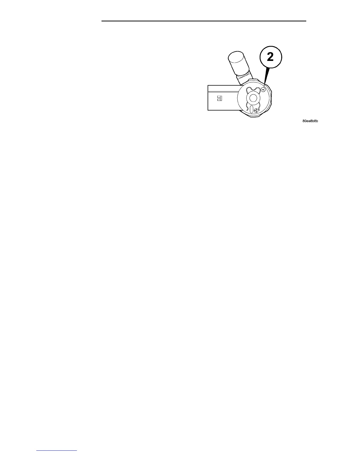
Classified injectors can be recognized by the part
number and identification on the magnetic head (cir-
cle with a number between 1 and 3 inside) (Fig. 9).
The number corresponds to the classification stage.
These general conditions equally apply if, as a
result of replacing an engine, carrying out repairs to
the cylinder head etc., the cylinder selective assign-
ment of the injectors or the engine control module
assignment may have changed. If proper attention is
not paid to the classification on these vehicles drive-
ability and smoking concerns could result.
If an injector is replaced, it is then necessary to
assign the classification number to the corresponding
cylinder with the DRBIIIt in the control module.
INJECTOR CLASSIFICATION PROCEDURE
(1) Turn ignition switch “ON”.
(2) Using a DRB IIIt and select ENGINE then
MISCELLANEOUS.
(3) Select LEARN INJECTORS.
(4) Using the up and down arrows, scroll to the
appropriate injector.
(5) Using the right and left arrows, set injector to
proper classification.
(6) Once injectors are classified, cycle ignition to
complete.
STANDARD PROCEDURE - CLEANING FUEL
INJECTORS
NOTE: Before cleaning the injector recesses, seal
the injector holes in the injector recesses with the
appropriate pin to prevent debris from falling into
the recesses and entering the motor.
(1) Seal the injector holes inside the cylinder head
recesses.
(2) Wipe out injector recesses with a non-woven
cloth, then clean with a cylinder brush.
(3) Clean the bottom of the cylinder recess with a
round brush.
(4) Blow out the recess and clean again with a
non-woven cloth and cover over.
(5) Perform these steps for each injector recess.
NOTE: DO NOT clean the tip of the injector with a
wire brush. Use a non - woven cloth.
(6) Clean injector body with a wire brush.
(7) Clean injector tips with a non-woven cloth.
NOTE: Do Not apply antiseize lubricant to the injec-
tor nozzle area.
(8) Grease injector body with anti seize lubricant.
Fig. 9 INJECTOR CLASSIFICATION MARKINGS
14 - 22 FUEL INJECTION VA
FUEL INJECTOR (Continued)

 Loading...


