erase. Refer to the appropriate diagnostic informa-
tion to diagnose any stored DTC that will not erase.
If the stored DTC information is successfully erased,
go to Step 9.
(9) Turn the ignition switch to the Off position for
about fifteen seconds, and then back to the On posi-
tion. Observe the airbag indicator in the instrument
cluster. It should illuminate for four seconds, then go
out. This indicates that the supplemental restraint
system is functioning normally and that the repairs
are complete. If the airbag indicator fails to light, or
lights and stays on, there is still an active supple-
mental restraint system fault or malfunction. Refer
to the appropriate diagnostic information to diagnose
the problem.
NOTE: If the Airbag Control Module (ACM) has been
replaced with a new unit, it will be necessary to ini-
tialize the new ACM. In order to function properly,
the ACM must be programmed for the correct stan-
dard and optional supplemental restraint system
components installed in the vehicle. To initialize the
ACM, a DRBIIIT scan tool is required. Refer to the
appropriate diagnostic information.
AIRBAG CONTROL MODULE
DESCRIPTION
The Airbag Control Module (ACM) is secured with
three screws to the top mounting surface of a
stamped steel bracket that is welded onto the floor
panel within the seat riser underneath the driver
side front seat in the passenger compartment of the
vehicle (Fig. 6). A molded plastic protective cover is
installed over the ACM and secured with integral
snap features to a flat metal base plate sandwiched
between the bottom of the ACM and the mounting
bracket on the floor panel (Fig. 7). This cover is
designed to shield the ACM and its wire harness con-
nection from other electrical components and wiring
located within the seat riser area beneath the driver
seat, and must always be reinstalled following ser-
vice removal.
Concealed within a hollow in the center of the die
cast white metal ACM housing is the electronic cir-
cuitry of the ACM which includes a microprocessor,
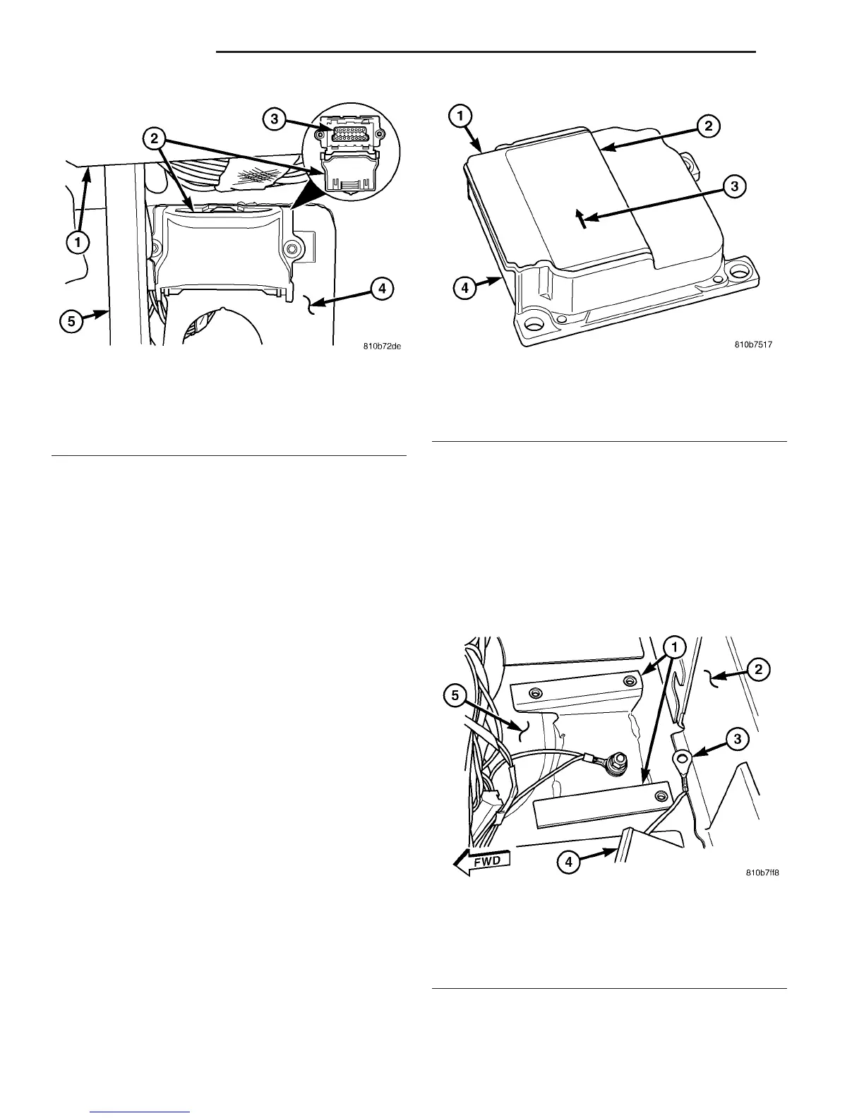
Fig. 5 16-Way Data Link Connector
1 - BOTTOM OF INSTRUMENT PANEL
2 - CONNECTOR COVER
3 - 16-WAY DATA LINK CONNECTOR
4 - DASH PANEL
5 - INSIDE HOOD RELEASE LEVER
Fig. 6 Airbag Control Module
1 - AIRBAG CONTROL MODULE
2 - LABEL
3 - ORIENTATION ARROW
4 - CONNECTOR RECEPTACLE
Fig. 7 ACM Bracket
1 - ACM BRACKET
2 - SEAT RISER
3 - EYELET TERMINAL
4 - ACM CONNECTOR
5 - FLOOR PANEL
8O - 8 RESTRAINTS VA
RESTRAINTS (Continued)

 Loading...


