(2) If servicing the driver side air outlets, remove
the instrument cluster bezel (Refer to 23 - BODY/IN-
STRUMENT PANEL/CLUSTER BEZEL - REMOV-
AL).
(3) If servicing the passenger side air outlets,
remove the passenger side airbag (Refer to 8 - ELEC-
TRICAL/RESTRAINTS/PASSENGER AIRBAG -
REMOVAL).
(4) If servicing the passenger side air outlets,
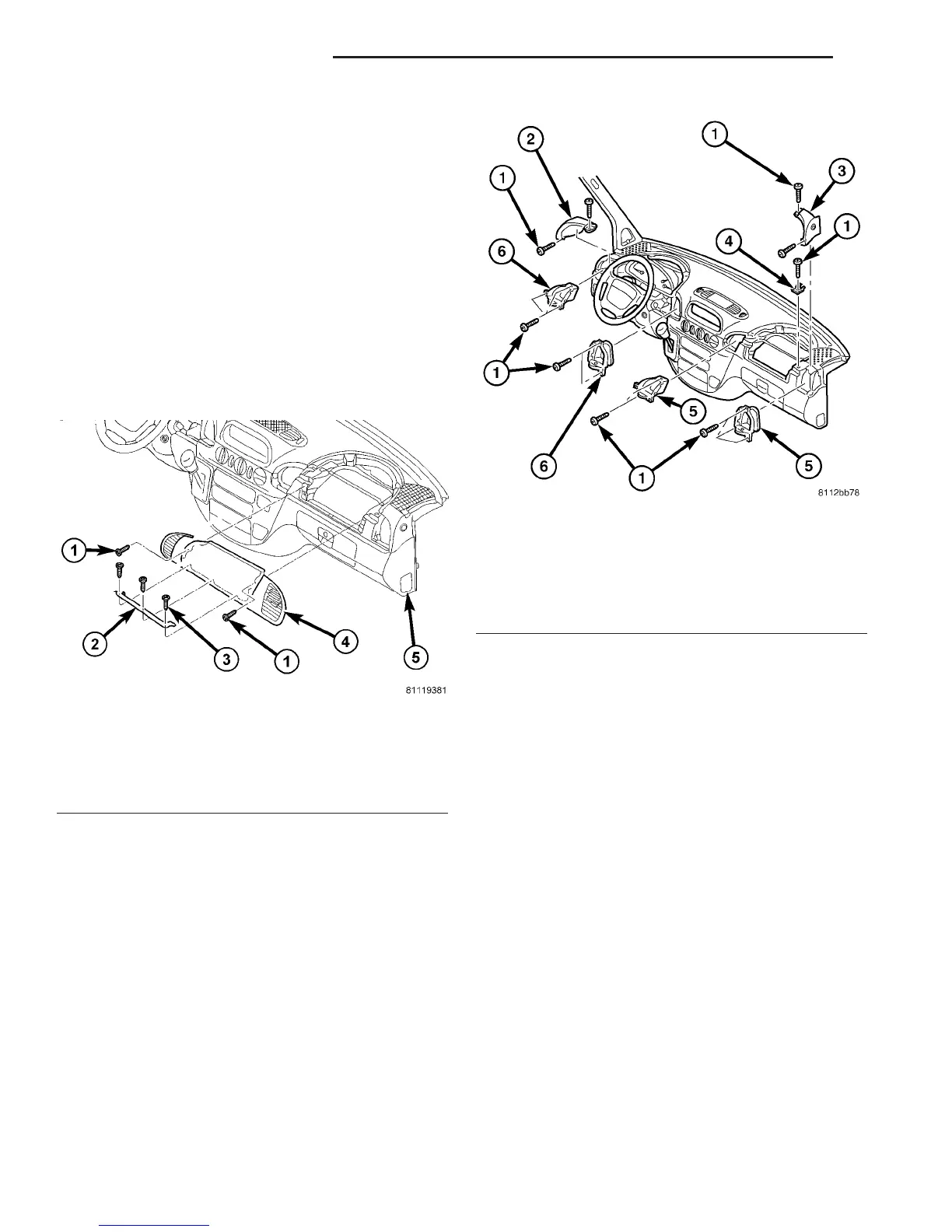
remove the passenger side air nozzle reinforcing
plate screws and the reinforcing plate (Fig. 2).
(5) If servicing the passenger side air outlets,
remove the passenger side air nozzle assembly using
a trim stick or other suitable wide flat blade tool,
until the snap features on the nozzle assembly are
released.
(6) If servicing the passenger side air outlets,
remove the air outlet retaining bracket from the
right side of the instrument panel (Fig. 3).
(7) Remove the instrument panel end cover screws
and the left and/or right side cover.
(8) Remove the air outlet retaining screws and the
air outlets as required.
INSTALLATION
(1) Install the air outlets and retaining screws as
required. Tighten the screws to 2 N·m (17 in. lbs.).
(2) Install the left and/or right side instrument
panel end cover and retaining screws as required.
Tighten the screws to 2 N·m (17 in. lbs.).
(3) If servicing the passenger side air outlets,
install the air outlet retaining bracket to the right
side of the instrument panel. Tighten the screw to 2
N·m (17 in. lbs.).
(4) If servicing the passenger side air outlets,
install the passenger side air nozzle assembly by
pressing the nozzle assembly firmly and evenly into
the instrument panel, until the snap features are
fully engaged.
(5) If servicing the passenger side air outlets,
install the passenger side air nozzle reinforcing plate
and retaining screws. Tighten the screws to 2 N·m
(17 in. lbs.).
(6) If servicing the passenger side air outlets,
install the passenger side airbag (Refer to 8 - ELEC-
TRICAL/RESTRAINTS/PASSENGER AIRBAG -
INSTALLATION).
(7) If servicing the driver side air outlets, install
the instrument cluster bezel (Refer to 23 - BODY/IN-
STRUMENT PANEL/CLUSTER BEZEL - INSTAL-
LATION).
(8) Reconnect the battery negative cable.
BLOWER MOTOR
REMOVAL
(1) Disconnect and isolate the negative battery
cable.
(2) Remove the engine air cleaner housing cover
(Refer to 9 - ENGINE/AIR INTAKE SYSTEM/AIR
CLEANER ELEMENT - REMOVAL).
Fig. 2 Passenger Side Air Nozzle Cover
1 - FRONT SCREWS (2)
2 - BRACKET
3 - BRACKET SCREWS
4 - NOZZLE COVER
5 - INSTRUMENT PANEL
Fig. 3 Instrument Panel Air Outlets
1 - SCREW (15)
2 - LH END COVER
3 - RH END COVER
4 - BRACKET
5 - PASSENGER SIDE AIR OUTLET (2)
6 - DRIVER SIDE AIR OUTLET (2)
24 - 32 DISTRIBUTION - FRONT VA
AIR OUTLETS (Continued)

 Loading...


