GENERATOR
DESCRIPTION
The generator is belt-driven by the engine using a
serpentine-type drive belt. It is serviced only as a
complete assembly. If the generator fails for any rea-
son, the entire assembly must be replaced.
On certain engines, the decoupler pulley may be
replaced separately.
OPERATION
As the energized rotor begins to rotate within the
generator, the spinning magnetic field induces a cur-
rent into the windings of the stator coil. Once the
generator begins producing sufficient current, it also
provides the current needed to energize the rotor.
The stator winding connections deliver the induced
AC current to 3 positive and 3 negative diodes for
rectification. From the diodes, rectified DC current is
delivered to the vehicle electrical system through the
generator battery terminal.
Although the generators appear the same exter-
nally, different generators with different output rat-
ings are used on this vehicle. Be certain that the
replacement generator has the same output rating
and part number as the original unit. Refer to Spec-
ifications and see Generator Ratings for amperage
ratings and part numbers.
Noise emitting from the generator may be caused
by: worn, loose or defective bearings; a loose or defec-
tive drive pulley (decoupler pulley); incorrect, worn,
damaged or misadjusted fan drive belt; loose mount-
ing bolts; a misaligned drive pulley or a defective sta-
tor or diode.
An instrument panel mounted, battery charge indi-
cator lamp is used. When the key is in the on posi-
tion, the lamp will be illuminated. This is done as a
bulb check. If this lamp remains illuminated while
the engine is running, a Diagnostic Trouble Code
(DTC) has been detected for the charging system.
REMOVAL
CAUTION: DISCONNECT NEGATIVE CABLE FROM
BATTERY BEFORE REMOVING BATTERY OUTPUT
WIRE FROM GENERATOR. FAILURE TO DO SO
CAN RESULT IN INJURY.
CAUTION: Never force a belt over a pulley rim
using a screwdriver. The synthetic fiber of the belt
can be damaged.
CAUTION: When installing a serpentine accessory
drive belt, the belt MUST be routed correctly. The
water pump will be rotating in the wrong direction if
the belt is installed incorrectly, causing the engine
to overheat. Refer to belt routing label in engine
compartment, or refer to Belt Schematics in Cooling
System.
(1) Disconnect and isolate negative battery cable.
(2) Remove generator drive belt. Refer to Cooling
System for procedure.
(3) Raise and support vehicle.
(4) Remove protective plastic cover from B+ stud
at top of generator.
(5) Remove nut securing battery output cable to
B+ terminal at top of generator.
(6) Unplug field terminal connector at rear of gen-
erator.
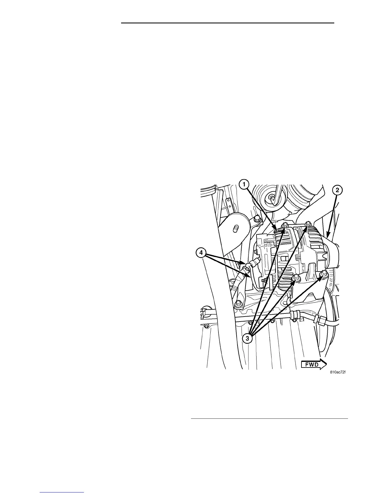
(7) Remove 4 generator mounting bolts (Torx-style
#12 bit) (Fig. 1).
(8) Remove generator from lower side of vehicle.
INSTALLATION
(1) Raise and support vehicle.
(2) Position generator to engine.
(3) Install 4 generator mounting bolts (Fig. 1).
Refer to Torque Specifications.
Fig. 1 GENERATOR MOUNTING - 2.7L DIESEL
1 - GENERATOR
2 - DRIVE BELT
3 - MOUNTING BOLTS (4)
4 - GENERATOR WIRING HARNESS
8F - 18 CHARGING SYSTEM VA

 Loading...


