(15) If vibration remains unacceptable, preform
the procedure to the front end of the propeller shaft.
(16) Install the wheel and tires. Lower the vehicle.
PROPELLER SHAFT RUNOUT
(1) Clean the propeller shaft surface where the
dial indicator will contact the shaft.
(2) The dial indicator must be installed perpendic-
ular to the shaft surface.
(3) Measure runout at the center and ends of the
shaft away from weld areas, to ensure weld process
will not effect the measurements.
(4) Refer to Runout Specifications chart.
(5) If propeller shaft is out of specification, remove
propeller shaft and index the shaft 180°. Install the
propeller shaft and measure shaft runout again.
(6) If propeller shaft is now within specifications,
mark shaft and yokes for proper orientation.
(7) If propeller shaft runout is not within specifica-
tions, check runout of the transmission and axle.
Correct as necessary and repeat propeller shaft
runout measurement.
(8) Replace propeller shaft if the runout still
exceeds the limits.
RUNOUT SPECIFICATIONS
Front of Shaft 0.020 in. (0.50 mm)
Center of Shaft 0.025 in. (0.63 mm)
Rear of Shaft 0.020 in. (0.50 mm)
note:
Measure front/rear runout approximately 76 mm (3 in.)
from the weld seam at each end of the shaft tube for
tube lengths over 30 inches. For tube lengths under
30 inches, the maximum allowed runout is 0.50 mm
(0.020 in.) for the full length of the tube.
STANDARD PROCEDURE
PROPELLER SHAFT ANGLE
This procedure applies the front and rear propeller
shafts.
(1) Place vehicle in netural.
(2) Raise and support vehicle at the axles as level
as possible.
(3) Remove universal joint snap rings if equipped,
so Inclinometer 7663 base sits flat.
(4) Rotate shaft until transmission case output
yoke bearing is facing downward.
NOTE: Always make measurements from front to
rear and from the same side of the vehicle.
(5) Place Inclinometer 7663 on yoke bearing (A)
parallel to the shaft. Center bubble in sight glass and
record measurement.
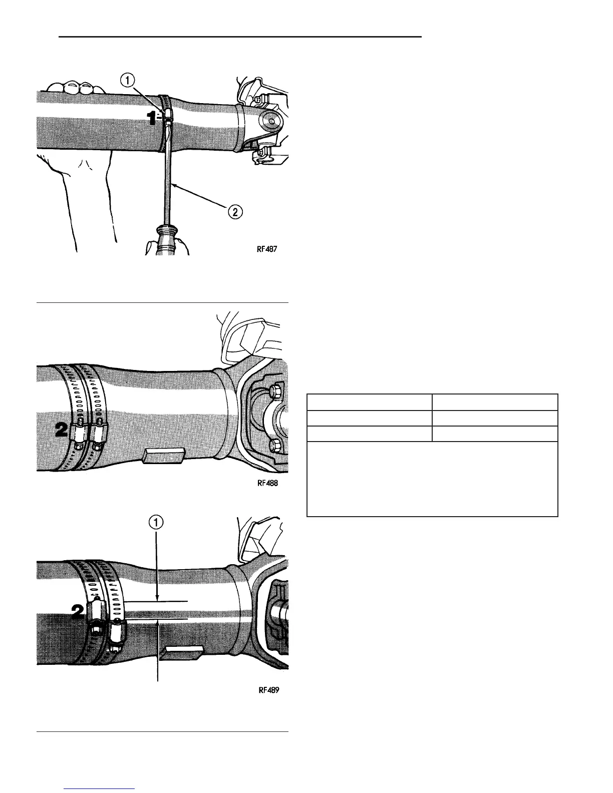
Fig. 1 Clamp Screw At Position 1
1 - CLAMP
2 - SCREWDRIVER
Fig. 2 Two Clamp Screws At The Same Position
Fig. 3 Clamp Screws Separated
1-
1
⁄
2
INCH
VA PROPELLER SHAFT 3 - 3
PROPELLER SHAFT (Continued)

 Loading...


