and the grommet seal, which is a light press fit. An
integral electrical connector receptacle is located on
the top of the motor housing.
An optional version of the washer pump/motor unit
incorporates an integral washer fluid level switch.
This version can be distinguished from models with-
out the switch by a vent nipple at the top of the
switch housing that is connected to a vent hose that
is retained in an integral clip behind the filler cap
near the top of the reservoir, and by a third terminal
pin in the washer pump/motor connector receptacle.
The washer pump/motor unit cannot be repaired. If
faulty or damaged, the entire washer pump/motor
unit must be replaced.
OPERATION
The washer pump/motor unit is connected to the
vehicle electrical system through a single take out
and connector of the vehicle wire harness. The
washer pump/motor is grounded at all times through
a take out of the vehicle wire harness with a single
eyelet terminal connector that is secured under a
ground screw located near the right headlamp in the
engine compartment. The washer pump/motor
receives battery current on a washer switch sense
circuit through the closed contacts of the momentary
washer switch circuitry within the multi-function
switch. When the pump motor is energized, the rotor-
type pump pressurizes the washer fluid and forces it
through the pump outlet nipple, the washer plumb-
ing, and the washer nozzles onto the windshield
glass. The washer pump/motor unit can be diagnosed
using conventional diagnostic tools and methods.
REMOVAL
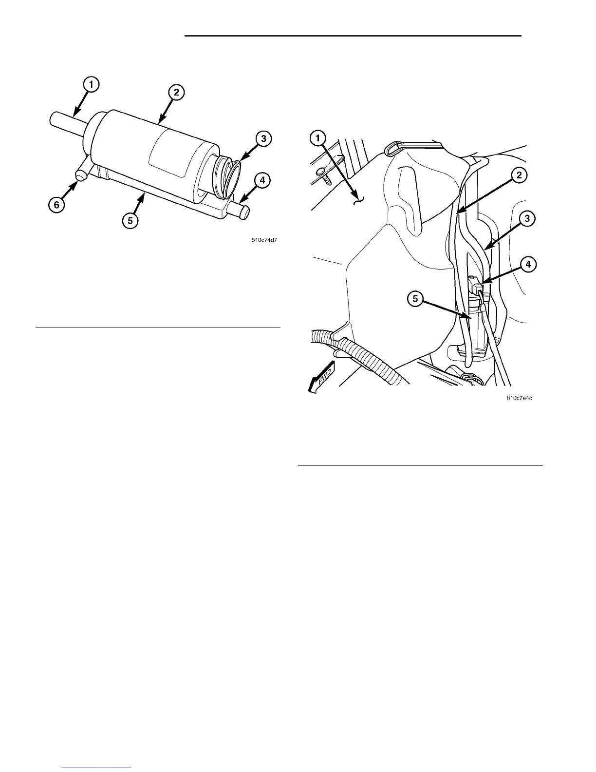
(1) Disconnect the vehicle wire harness connector
for the washer pump/motor from the motor connector
receptacle (Fig. 10).
(2) Disconnect the washer supply hose from the
barbed outlet nipple of the washer pump/motor and
allow the washer fluid to drain into a clean container
for reuse.
(3) If the vehicle is so equipped, disconnect the
washer fluid level switch vent hose from the barbed
vent nipple near the top of the washer pump/motor
unit.
(4) Using hand pressure, firmly grasp and pull the
washer pump out of the rubber grommet seal in the
reservoir. Care must be taken not to damage the res-
ervoir.
(5) Remove the rubber grommet seal from the
washer pump mounting hole in the washer reservoir
and discard.
INSTALLATION
(1)
Install a new rubber grommet seal into the
washer pump mounting hole in the washer reservoir.
Always use a new rubber grommet seal on the reservoir.
(2) Position the inlet nipple of the washer pump to
the rubber grommet seal in the reservoir.
Fig. 9 Washer Pump/Motor
1 - INLET NIPPLE
2 - WASHER PUMP/MOTOR
3 - CONNECTOR RECEPTACLE
4 - VENT NIPPLE (W/FLUID LEVEL SWITCH ONLY)
5 - WASHER FLUID LEVEL SWITCH HOUSING
6 - OUTLET NIPPLE
Fig. 10 Washer Pump/Motor Remove/Install
1 - WASHER RESERVOIR
2 - WASHER SUPPLY HOSE
3 - VENT HOSE (W/FLUID LEVEL SWITCH ONLY)
4 - WIRE HARNESS CONNECTOR
5 - WASHER PUMP/MOTOR
8R - 10 WIPERS/WASHERS VA
WASHER PUMP/MOTOR (Continued)

 Loading...


