GEARSHIFT CABLE
DIAGNOSIS AND TESTING - GEARSHIFT
CABLE
(1) The floor shifter lever and gate positions
should be in alignment with all transmission PARK,
NEUTRAL, and gear detent positions.
(2) Engine starts must be possible with floor shift
lever in PARK or NEUTRAL gate positions only.
Engine starts must not be possible in any other gear
position.
(3) With floor shift lever handle push-button not
depressed and lever in:
(a) PARK position - Apply forward force on cen-
ter of handle and remove pressure. Engine starts
must be possible.
(b) PARK position - Apply rearward force on cen-
ter of handle and remove pressure. Engine starts
must be possible.
(c) NEUTRAL position - Normal position. Engine
starts must be possible.
(d) NEUTRAL position - Engine running and
brakes applied, apply forward force on center of
shift handle. Transmission shall not be able to shift
from NEUTRAL to REVERSE.
REMOVAL
(1) Move selector lever to position 9D9.
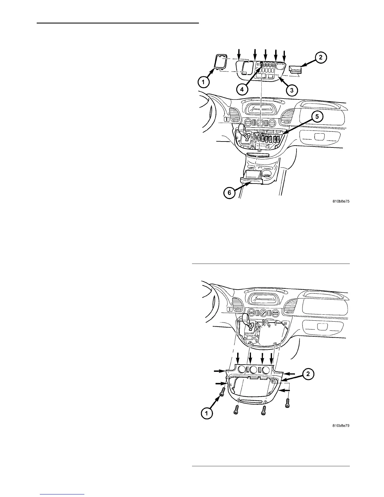
(2) Remove top (3) (Fig. 146) of the center section
of instrument panel.
(3) Remove bottom (2) (Fig. 147) of the center sec-
tion of instrument panel.
(4) Pry ball socket of transmission shift cable off
ball knob at the shift lever assembly (SLA). Use a
suitable slotted screwdriver.
(5) Raise and support vehicle.
(6) Detach shift cable at transmission.
(a) Unlatch ball socket latch (Fig. 148) of cable.
(b) Unclip shift cable retainer from retainer
bracket. When pulling out cable, press together
hooks of shift cable retainer at the points shown
(arrows).
(c) Pull shift cable out of ball socket. Ball socket
can remain on transmission lever.
(7) Remove the shift cable grommet from the dash
panel.
(8) Remove the shift cable from the vehicle.
INSTALLATION
(1) Pass the shift cable through the opening in the
dash panel and seat the shift cable grommet into the
hole.
(2) Install the shift cable (Fig. 149) to the trans-
mission.
Fig. 146 Remove Top Section Of Center Instrument
Panel
1 - SHIFT LEVER ASSEMBLY FRAME TRIM
2 - STORAGE COMPARTMENT
3 - TOP CENTER PART OF INSTRUMENT PANEL
4 - SCREW
5 - PLUG CONNECTIONS
6 - ASHTRAY
Fig. 147 Remove Bottom Section Of Center
Instrument Panel
1 - SCREW
2 - BOTTOM CENTER PART OF INSTRUMENT PANEL
VA AUTOMATIC TRANSMISSION - NAG1 21 - 109

 Loading...


