HUB / BEARING
DIAGNOSIS AND TESTING -
(1) Raise and support the vehicle.
(2) Remove the grease cap.
(3) Position a dial indicator against the face of the
wheel hub (Fig. 3).
(4) Tighten the locking screw on the clamping nut
(Fig. 3).
(5) Pull the wheel hub firmly back and forth and
read off the wheel bearing play on the dial gauge.
(Wheel bearing play should be 0.02 - 0.04 mm
(0.000787 - 0.00158 in.).
(6) If necessary, loosen the locking screw and
adjust the wheel bearing play by loosing or tighten-
ing the clamping nut.
(7) Retighten the locking screw and recheck the
wheel bearing play.
REMOVAL
(1) Raise and support the vehicle.
(2) Remove the front wheels (Refer to 22 - TIRES/
WHEELS/WHEELS - REMOVAL).
(3) Remove the disc brake caliper adapter (Refer to
5 - BRAKES/HYDRAULIC/MECHANICAL/DISC
BRAKE CALIPER ADAPTER - REMOVAL).
(4) Remove the wheel flange ring (if equipped with
dual rear wheels) (Fig. 5).
(5) Remove the disc brake rotor (Refer to 5 -
BRAKES/HYDRAULIC/MECHANICAL/ROTORS -
REMOVAL).
(6) Remove the grease cap (Fig. 4).
(7) Loosen the bolt on the clamping nut and
remove the clamping nut (Fig. 4).
(8) Remove the thrust washer (Fig. 4).
(9) Remove the wheel hub and tapered roller bear-
ing from the stub axle assembly (Fig. 4).
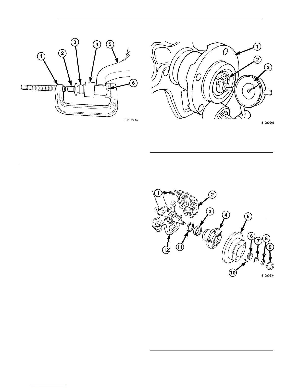
Fig. 2 LCA BUSHING INSTALL
1 - SPECIAL TOOL C-4212F (PRESS)
2 - SPECIAL TOOL 9302-1 (DRIVER)
3 - BUSHING
4 - SPECIAL TOOL 9302-2 (SIZER CUP)
5 - LOWER CONTROL ARM
6 - SPECIAL TOOL 9302-4 (RECEIVER CUP)
Fig. 3 MEASURING & ADJUSTING WHEEL BEARING
1 - WHEEL HUB
2 - LOCKING SCREW
3 - DIAL INDICATOR
Fig. 4 FRONT WHEEL HUB WITH SINGLE REAR
WHEELS (SRW)
1 - CALIPER ADAPTER BOLT
2 - DISC BRAKE CALIPER
3 - INNER BEARING
4 - WHEEL HUB
5 - DISC BRAKE ROTOR
6 - OUTER BEARING
7 - THRUST WASHER
8 - CLAMPING NUT
9 - GREASE CAP
10 - LOCKING BOLT
11 - GREASE SEAL
12 - STEERING KNUCKLE
2 - 4 FRONT VA
BUSHINGS (Continued)

 Loading...


