(1) Disconnect and isolate the battery negative
cable.
(2) Move the driver side front seat to its most for-
ward position for easiest access to the seat riser
cover panel (Fig. 15).
(3) Remove the cover panel from the top of the
driver side seat riser.
(4) Remove the fog lamp relay by grasping it
firmly and pulling it straight out of the relay connec-
tor.
INSTALLATION
Fog lamps are optional equipment on this model.
On vehicles equipped with fog lamps, a fog lamp
relay is located in a dedicated connector of the vehi-
cle wire harness. This connector is snapped into an
opening in a stamped sheet metal bracket which is
secured with screws within the driver side front seat
riser just beneath the seat riser cover panel.
WARNING: ON VEHICLES EQUIPPED WITH AIR-
BAGS, DISABLE THE SUPPLEMENTAL RESTRAINT
SYSTEM BEFORE ATTEMPTING ANY STEERING
WHEEL, STEERING COLUMN, DRIVER AIRBAG,
PASSENGER AIRBAG, SEAT BELT TENSIONER, OR
INSTRUMENT PANEL COMPONENT DIAGNOSIS OR
SERVICE. DISCONNECT AND ISOLATE THE BAT-
TERY NEGATIVE (GROUND) CABLE, THEN WAIT
TWO MINUTES FOR THE SYSTEM CAPACITOR TO
DISCHARGE BEFORE PERFORMING FURTHER
DIAGNOSIS OR SERVICE. THIS IS THE ONLY SURE
WAY TO DISABLE THE SUPPLEMENTAL
RESTRAINT SYSTEM. FAILURE TO TAKE THE
PROPER PRECAUTIONS COULD RESULT IN ACCI-
DENTAL AIRBAG DEPLOYMENT AND POSSIBLE
PERSONAL INJURY.
(1) Position the fog lamp relay to the relay connec-
tor.
(2) Align the fog lamp relay terminals with the
terminal cavities in the relay connector.
(3) Using hand pressure, push firmly and evenly
on the top of the fog lamp relay until the terminals
are fully seated in the relay connector.
(4) Position the cover panel onto the top of the
driver side seat riser (Fig. 15).
(5) Install and tighten the two screws that secure
the cover panel to the top of the seat riser under the
driver side front seat.
(6) Move the driver side front seat back to its driv-
ing position.
(7) Reconnect the battery negative cable.
FOG LAMP SWITCH
REMOVAL
(1) Disconnect and isolate the battery negative
cable.
(2) Remove the cluster bezel from the instrument
panel (Fig. 16). (Refer to 23 - BODY/INSTRUMENT
PANEL/CLUSTER BEZEL - REMOVAL).
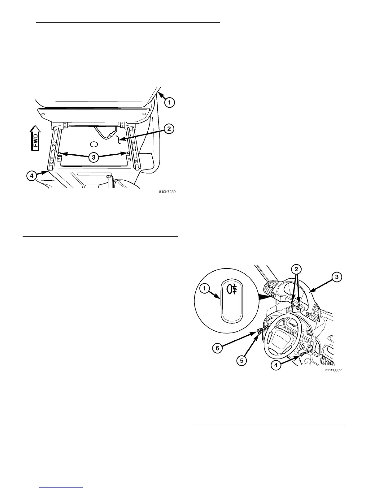
Fig. 15 Seat Riser Cover
1 - DRIVER SEAT BACK
2 - COVER PANEL
3 - SCREW (2)
4 - SEAT RISER
Fig. 16 Fog Lamp Switch
1 - FOG LAMP SWITCH
2 - SCREW (2)
3 - CLUSTER BEZEL
4 - TO REAR WINDOW DEFOGGER SWITCH (OPTION AL)
5 - TO HEADLAMP LEVELING SWITCH
6 - TO FOG LAMP SWITCH (OPTIONAL)
VA LAMPS/LIGHTING - EXTERIOR 8L - 11
FOG LAMP RELAY (Continued)

 Loading...


