(7) Install the right intake manifold support brack-
ets. Tighten the bolts to 14 N·m (124 lbs. in.) (Fig.
63).
(8) Install the lower intake manifold support
bracket. Tighten bolts to 20 N·m (177 lbs. in.) (Fig.
63).
(9) Connect both fuel lines to fuel filter assembly
(Refer to 14 - FUEL SYSTEM/FUEL DELIVERY/
FUEL FILTER - INSTALLATION).
(10) Connect the coolant hose at the connection
junction above the lower intake manifold support
bracket (Fig. 63).
(11) Secure the engine wiring harness and cable
duct to the intake manifold (Fig. 63).
(12) Connect the EGR wiring harness connector
(Fig. 63).
(13) Connect the charge air hose to the intake
manifold (Fig. 63).
(14) Carefully route the engine wiring harness
through and into the passenger compartment and
reconnect.
(15) Install the engine cover.
(16) Fill the cooling system.
(17) Connect the negative battery cable.
(18) Start the engine and inspect for leaks. Care
must be taken to observe the fuel system warnin-
g.(Refer to 14 - FUEL SYSTEM - WARNING).
EXHAUST MANIFOLD
REMOVAL
(1) Remove the turbocharger (Refer to 11 -
EXHAUST SYSTEM/TURBOCHARGER SYSTEM/
TURBOCHARGER - REMOVAL).
(2) Remove the self locking exhaust manifold nuts
(Fig. 64).
(3) Remove exhaust manifold and clean mating
surfaces (Fig. 64).
INSTALLATION
NOTE: Exhaust manifold surface must be flat within
0.006 in. per foot (0.15mm per 300mm) of manifold
length.
(1) Inspect exhaust manifold gasket surface for
flatness with a straight edge (Fig. 64).
(2) Inspect exhaust manifold for cracks or distor-
tion (Fig. 64).
(3) Install new exhaust manifold gasket (Fig. 64).
(4) Position the exhaust manifold over to studs
and tighten retaining nuts to 22 lbs. ft. (30 N·m (Fig.
64)).
(5) Install turbocharger (Refer to 11 - EXHAUST
SYSTEM/TURBOCHARGER SYSTEM/TURBO-
CHARGER - INSTALLATION).
TIMING CHAIN COVER
REMOVAL
WARNING: DO NOT OPEN COOLING SYSTEM
UNLESS TEMPERATURE IS BELOW 90°C (194°F).
OPEN CAP SLOWLY TO RELEASE PRESSURE.
STORE COOLANT IN APPROVED CONTAINER
ONLY. RISK OF INJURY TO SKIN AND EYES FROM
SCALDING COOLANT. WEAR PROTECTIVE
GLOVES, CLOTHING AND EYE WEAR.
(1) Disconnect negative battery cable.
NOTE: Rotate engine on crankshaft. DO NOT crank
the engine at the bolt of the camshaft sprocket.
NOTE: DO NOT crank engine back.
(2) Position piston of cylinder 1 to ignition TDC.
Markings on the camshaft bearing cap must be
aligned.
(3) Drain coolant (Refer to 7 - COOLING/ENGINE/
COOLANT - STANDARD PROCEDURE).
(4) Install retaining lock for crankshaft/starter
ring gear (Refer to 9 - ENGINE/ENGINE BLOCK/
FLEX PLATE - INSTALLATION).
(5) Drain engine oil.
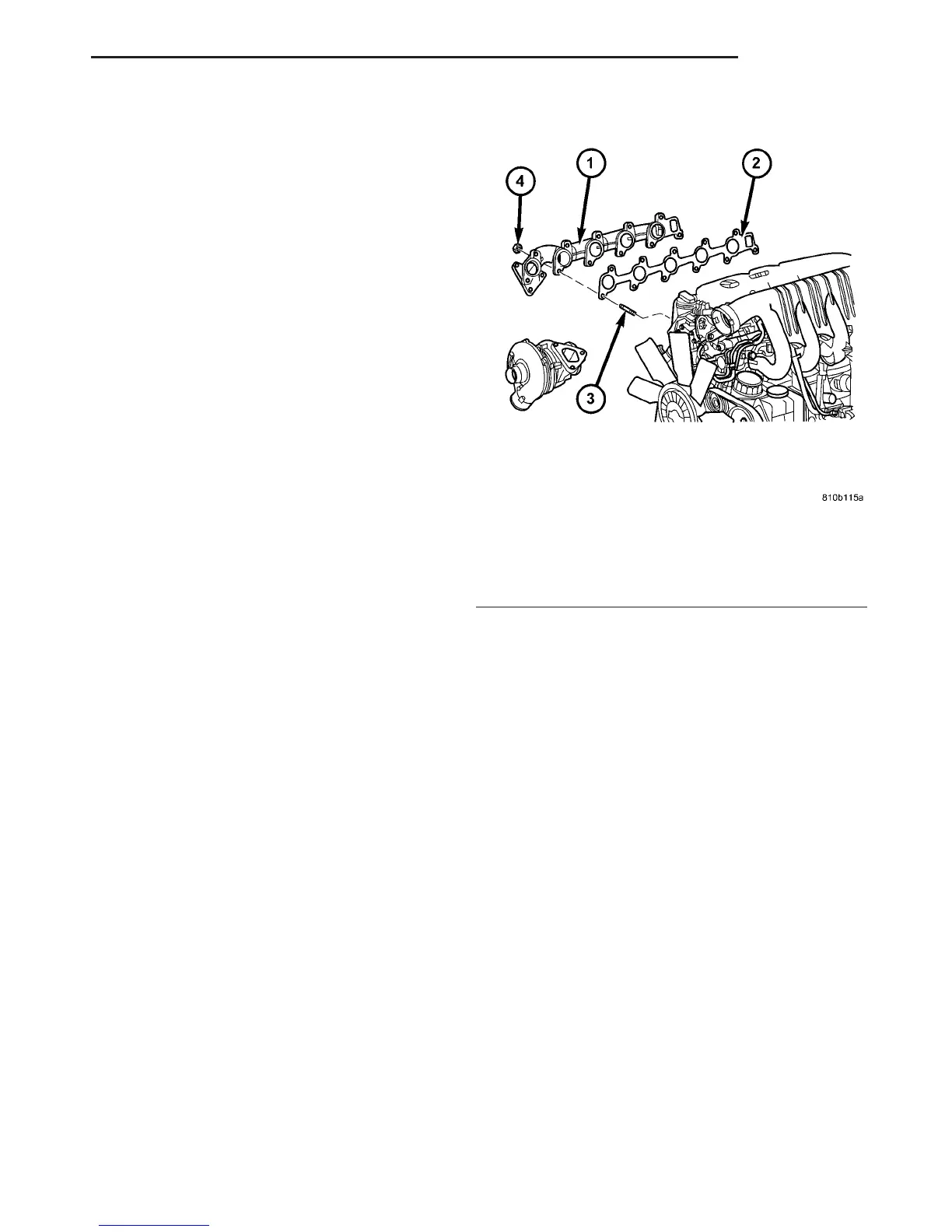
Fig. 64 EXHAUST MANIFOLD
1 - EXHAUST MANIFOLD
2 - GASKET
3 - STUD
4 - NUT
VA ENGINE 9 - 59
INTAKE MANIFOLD (Continued)

 Loading...


