(5) Carefully raise locking pawl of top slide rail
and remove front cover at cylinder head (Fig. 15).
(6) Insert a locking pin through 1st camshaft bear-
ing cap into the hole in the inlet camshaft sprocket.
(7) Counter hold the camshaft with an open end
wrench to avoid damage and unbolt driver of inlet
camshaft sprocket.
(8) Remove top guide rail.
INSTALLATION
INSTALLATION - CYLINDER HEAD
WARNING: (Refer to 14 - FUEL SYSTEM - WARN-
ING)
NOTE: Thoroughly clean all mating surfaces with
appropriate solvents and blow out bolt holes, to
assure that no grease or oil is present during reas-
sembly.
NOTE: If piston or connecting rods have been
replaced, measure piston protrusion.
NOTE: Check facing cylinder head contact surface.
(1) Position the cylinder head and gasket properly
on engine using the dowel pins as guide (Fig. 14).
NOTE: Inspect all cylinder head bolts for defects
and stretching before installation (Refer to 9 -
ENGINE/CYLINDER HEAD - STANDARD PROCE-
DURE).
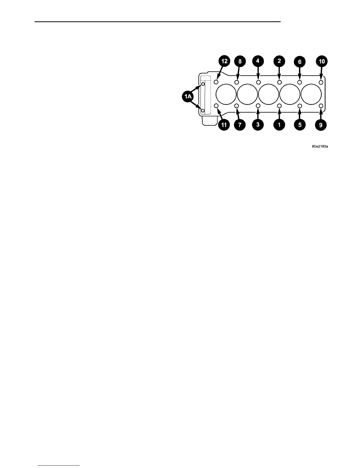
CYLINDER HEAD BOLT TORQUE SEQUENCE
The M12 cylinder head bolts must be torqued
in 3 stages.
(1) Install M12 cylinder head bolts finger tight
(Fig. 14).
(2) Torque bolts in numeric order starting with
number 1 to 60 N·m (44 lbs.in.) (Fig. 16).
(3) Install M8 timing chain cover to cylinder head
bolts. Tighten to 20N·m (177 lbs.in.).
(4) Tighten M12 cylinder head bolts in numeric
order starting with number 1 an additional 90° (Fig.
16).
(5) Tighten M12 cylinder head bolts in numeric
order starting with number 1 an additional 90° again
(3 stages). (Fig. 16).
(2) Install fuel return flow line between rail and
high pressure pump (Fig. 13).
(3) Connect the coolant hoses to the thermostat
housing (Fig. 13).
(4) Connect the coolant pipe at the cylinder head
(Fig. 13).
(5) Reconnect transmission oil dip stick tube.
Tighten to 14 N·m (124 lbs. in.) (Fig. 13).
(6) Reconnect the turbocharger to the exhaust
manifold. Tighten to 30N·m (22 lbs.ft.) (Fig. 13).
(7) Install oil return flow line with new seals at
turbocharger. Tighten bolt of supply line to turbo-
charger to 18N·m (160 lbs. in.) and bolt of supply line
to cylinder head to 9N·m (80 lbs. in.) (Fig. 13)
(8) Install charge air distribution pipe (Refer to 11
- EXHAUST SYSTEM/TURBOCHARGER SYSTEM -
INSTALLATION).
(9) Install and properly route the engine wiring
harness, making appropriate connections.
(10) Install high pressure fuel pump intermediate
gear (Fig. 13).
(11) Install high pressure pump (Refer to 14 -
FUEL SYSTEM/FUEL DELIVERY/FUEL INJEC-
TION PUMP - INSTALLATION).
(12) Install the camshaft housing to cylinder head
(Fig. 13).
(13) Install the tappets (Fig. 13).
(14) Install camshafts (Refer to 9 - ENGINE/CYL-
INDER HEAD/CAMSHAFT(S) - INSTALLATION).
(15) Install top guide rail (Refer to 9 - ENGINE/
VALVE TIMING/TIMING BELT/CHAIN AND
SPROCKETS - INSTALLATION).
(16) Install front cover at cylinder head (Refer to 9
- ENGINE/CYLINDER HEAD - INSTALLATION).
(17) Install cylinder head cover (Refer to 9 -
ENGINE/CYLINDER HEAD/CYLINDER HEAD
COVER(S) - INSTALLATION).
(18) Install fuel high pressure pipes and injectors
(Refer to 14 - FUEL SYSTEM/FUEL INJECTION/
FUEL INJECTOR - INSTALLATION).
(19) Install timing chain tensioner with new gas-
ket. (Refer to 9 - ENGINE/VALVE TIMING/TIMING
Fig. 16 CYLINDER HEAD BOLT TORQUE
SEQUENCE
VA ENGINE 9 - 25
CYLINDER HEAD (Continued)

 Loading...


