(3) Position the ventilation housing insulation
blanket out of the way of the blower motor assembly.
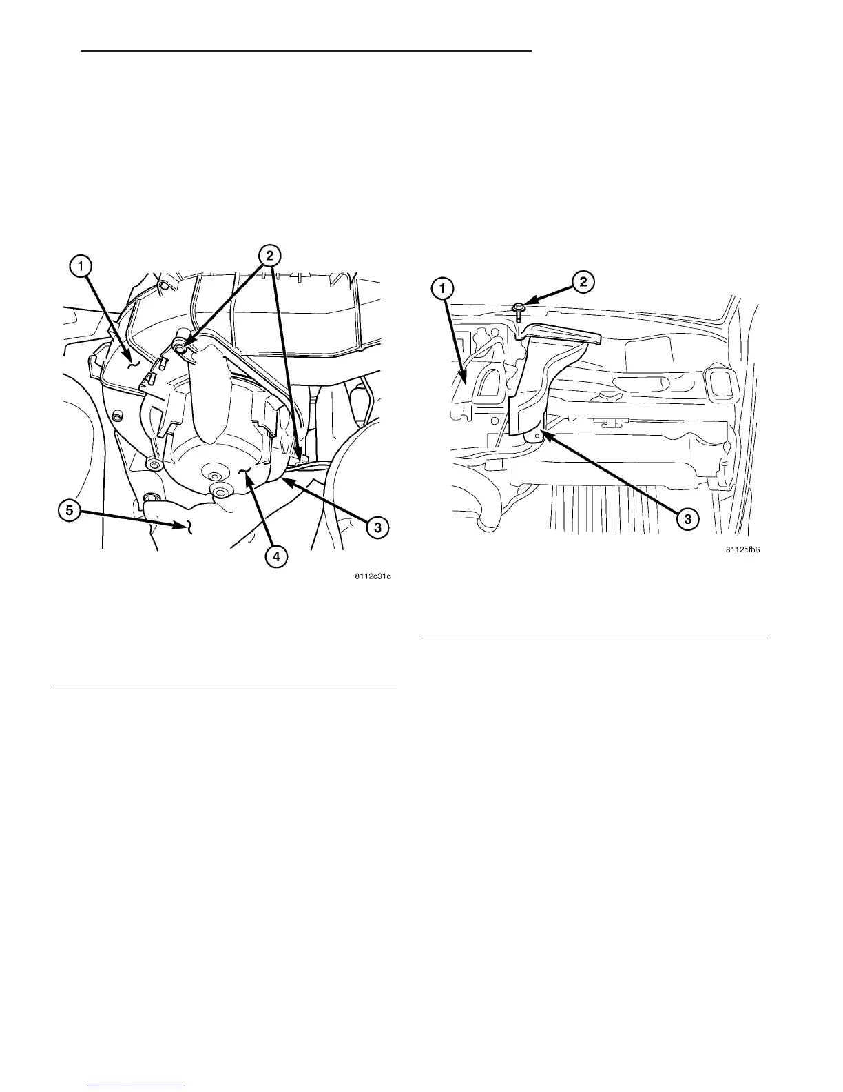
(4) Disconnect the wire harness connector from the
blower motor (Fig. 4).
(5) Remove the three blower motor retaining
screws.
(6) Remove the blower motor assembly from the
ventilation housing.
INSTALLATION
(1) Install the blower motor assembly into the ven-
tilation housing.
(2) Install the three blower motor retaining
screws. Tighten the screws to 2 N·m (17 in. lbs.).
(3) Connect the wire harness connector to the
blower motor.
(4) Install the ventilation housing insulation blan-
ket.
(5) Install the engine air cleaner cover (Refer to 9 -
ENGINE/AIR INTAKE SYSTEM/AIR CLEANER
HOUSING - INSTALLATION).
(6) Reconnect the negative battery cable.
DEFROSTER DUCTS
REMOVAL
(1) Remove the instrument panel (Refer to 23 -
BODY/INSTRUMENT PANEL - REMOVAL).
(2) Remove the screw that secures the left and/or
right side defroster duct to the heater housing,
depending on the duct being removed (Fig. 5).
(3) Remove the defroster duct(s) from the housing.
INSTALLATION
(1) Install the left and/or right side defroster duct
on to the heater housing.
(2) Install the screw that secures the defroster
duct to the housing. Tighten the screw(s) to 2 N·m
(17 in. lbs.).
(3) Install the instrument panel (Refer to 23 -
BODY/INSTRUMENT PANEL - INSTALLATION).
FLOOR DISTRIBUTION DUCTS
REMOVAL
(1) Remove the instrument panel (Refer to 23 -
BODY/INSTRUMENT PANEL/INSTRUMENT
PANEL ASSEMBLY - REMOVAL).
(2) Remove the defroster ducts (Refer to 24 -
HEATING & AIR CONDITIONING/DISTRIBUTION/
DEFROSTER DUCTS - REMOVAL).
(3) Remove the screws that secure the left and
right floor distribution ducts to the instrument panel
support (Fig. 6).
Fig. 4 Blower Motor Assembly
1 - VENTILATION HOUSING
2 - SCREWS (3)
3 - WIRE HARNESS CONNECTOR
4 - BLOWER MOTOR
5 - INSULATION BLANKET
Fig. 5 Defroster Duct - RH Shown, LH Typical
1 - HEATER HOUSING
2 - SCREW
3 - DEFROSTER DUCT
VA DISTRIBUTION - FRONT 24 - 33
BLOWER MOTOR (Continued)

 Loading...


