(16) Lower the jack and remove the transverse leaf
spring towards the side.
INSTALLATION
NOTE: To avoid damaging the transverse leaf
spring, cushion the pad on the jack accordingly.
NOTE: Hand tighten all bolts until vehicle is on the
ground, unless the bushings may become distorted.
NOTE: The height blocks between the engine cradle
and the spring are color coded, Make sure not to
mix the blocks per sides. The blocks are different in
sizes to accommodate the weight of the vehicle and
driver in order for the vehicle to sit level.
(1) Install the transverse leaf spring in the center
with a jack with all the rubber mounts attached.
(2) Install the lower control arm to the frame (Fig.
9).
(3) Install the knuckle on the lower ball joint.
(4) Raise the lower control arm approximately 10
mm with a jack.
(5) Install both stop plate bolts to the lower control
arm
(6) Install the strut bolts to the steering knuckle.
(7) Reinstall the tie rod to the steering knuckle
(Fig. 9). Tighten to 150 N·m (110 ft. lbs.).
(8) Install the ABS sensor all the way into the
steering knuckle, the sensor will adjust automatically
when the vehicle is moved (Fig. 9).
(9) Install the disc brake caliper adapter (Fig. 9).
Tighten to 170 N·m (125 ft. lbs.).
(10) Install the front wheels.
(11) Lower the vehicle.
(12) Install the spring clamp plates (Fig. 9).
Tighten (M-10 bolts) to 65 N·m (48 ft. lbs.) (M-12
bolts) to 130 N·m (96 ft. lbs.).
(13) Roll the vehicle approximately 1 mm forwards
and the backwards, and rock firmly.
(14) Tighten the nuts on the lower control arm to
the frame to 150 N·m (110 ft. lbs.).
(15) Apply brake to actuate brake pressure.
SPRING CLAMP PLATES
REMOVAL
(1) Raise and support the vehicle.
(2) Install a jack under the lower ball joint and
lower the weight of the vehicle enough to allow a
wrench between the lower control arm and the
bracket tighten the nut.
(3) Remove the front and rear bolts to the spring
clamp plates.
(4) Remove the four inner retaining bolts and
nuts.
(5) Remove the spring clamp plate and rubber
block.
(6) Remove the shear bushings from the front and
rear bolts.
INSTALLATION
(1) Install a jack under the lower ball joint and
lower the weight of the vehicle enough to allow a
wrench between the lower control arm and the
bracket tighten the nut.
(2) Fit one spring clamp plate together with the
lower spring rubber block.
(3) Install the bolt with the shear bushing on the
rear mounting, Do not tighten yet.
(4) Install the four retaining bolts for the spring
clamp plate. Tighten to 65 N·m (48 ft.lbs.).
(5) Align the holes for the front clamp plate joint
using a suitable drift (shear bushing not installed).
(6) Remove the alignment drift.
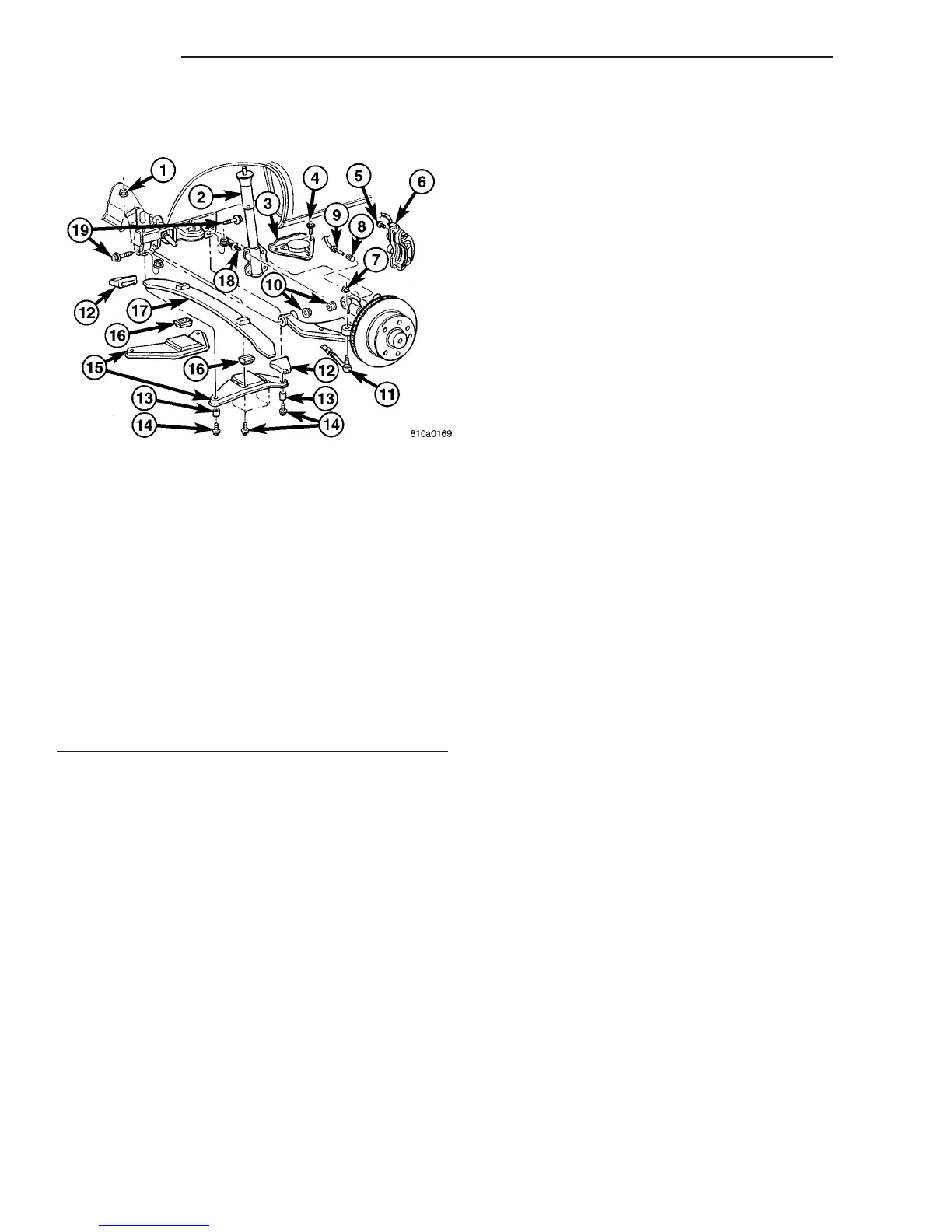
Fig. 9 FRONT SPRING
1 - NUT
2 - STRUT
3 - STOP PLATE
4 - STOP PLATE BOLT
5 - CALIPER ADAPTER BOLT
6 - DISC BRAKE CALIPER
7 - OUTER TIE ROD END NUT
8 - ABS SENSOR
9 - SPEED SENSOR
10 - LOWER CONTROL ARM RETAINING NUTS
11 - OUTER TIE ROD END
12 - RUBBER SPRING MOUNT
13 - SHEAR BUSHING
14 - SPRING CLAMP PLATE BOLT
15 - SPRING CLAMP PLATE
16 - LOWER RUBBER SPRING MOUNT
17 - SPRING
18 - STRUT BOLTS
19 - LOWER CONTROL ARM BOLTS
2 - 8 FRONT VA
SPRING (Continued)

 Loading...


