REMOVAL
REMOVAL
NOTE: Capture any fluid spillage and store in an
appropriately marked and suitable containers.
(1) Disconnect the negative battery cable.
(2) Remove the heat shield (Fig. 6).
(3) Separate the front exhaust pipe from the tur-
bocharger (Fig. 6)
(4) Separate the charge air and intake air hoses at
the turbocharger (Fig. 6).
(5) Remove the vacuum line from the turbocharger
vacuum unit (Fig. 6).
(6) Separate the oil supply at the cylinder head
and turbocharger (Fig. 6).
(7) Separate the oil return flow line at the turbo-
charger (Fig. 6).
(8) Remove the turbocharger support bracket (Fig.
6).
(9) Remove turbocharger from exhaust manifold
(Fig. 6).
REMOVAL - VACUUM TRANSDUCER
(1) Disconnect the negative battery cable.
(2) Remove the air cleaner housing (Refer to 9 -
ENGINE/AIR INTAKE SYSTEM/AIR CLEANER
HOUSING - REMOVAL).
(3) Disconnect the electrical connector.
(4) Disconnect the vacuum hoses.
(5) Remove the vacuum transducer retaining bolts
and remove vacuum transducer.
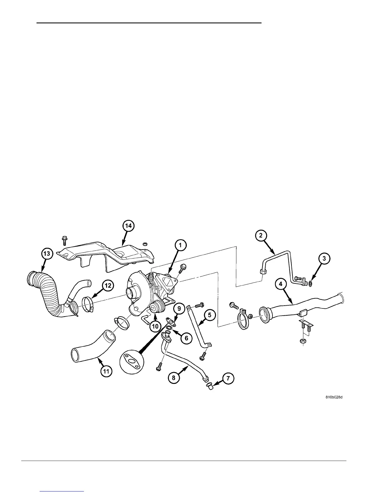
Fig. 6 TURBOCHARGER
1 - TURBOCHARGER 8 - OIL RETURN LINE
2 - OIL SUPPLY LINE 9 - GASKET
3 - O-RING 10 - VACUUM UNIT
4 - FRONT EXHAUST PIPE 11 - CHARGE AIR HOSE
5 - BRACKET 12 - CLAMP
6 - O-RING 13 - AIR INTAKE HOSE
7 - GASKET 14 - HEAT SHIELD
VA EXHAUST SYSTEM 11 - 7
TURBOCHARGER (Continued)

 Loading...


