(7) Connect negative battery cable.
CYLINDER HEAD
STANDARD PROCEDURE
STANDARD PROCEDURE - CYLINDER HEAD
BOLT INSPECTION
(1) Measure cylinder head bolts between points
shown (Fig. 11).
Cylinder Head
Bolts
Thread
Diameter
12 M
Length When
New
102 mm
Maximum
Length
104 mm
(2) If the cylinder head bolt length is greater than
the maximum allowable measurement, replace the
cylinder head bolts.
STANDARD PROCEDURE - MEASURE
CYLINDER HEAD SURFACE
NOTE: Only resurface cylinder head contact surface
if porous or damaged. IT IS NOT necessary to
rework minor variations in flatness in the longitudi-
nal direction.
(1) Disconnect negative battery cable.
(2) Remove cylinder head (Refer to 9 - ENGINE/
CYLINDER HEAD - REMOVAL).
(3) Remove valves.
(4) Inspect cylinder head contact surface for flat-
ness, porous and damage.
(5) Using a straight edge, measure cylinder head
and cylinder block flatness.
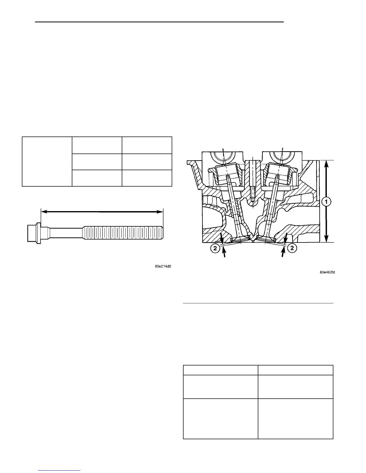
(6) Measure cylinder head height at point (1) indi-
cated and retain reading (Fig. 12).
NOTE: The camshaft housing Must Not be
machined. Basic bore of the camshaft bearings will
be altered.
(7) Machine cylinder head contact surface, if nec-
essary.
(8) Measure cylinder head height (1) at point indi-
cated, record stock removal (Fig. 12) CYLINDER
HEAD SPECIFICATIONS.
(9) Measure valve setback at points (2) indicated
(Fig. 12) CYLINDER HEAD SPECIFICATIONS.
NOTE: If measurement is less than dimension “2”
no further correct valve clearance compensation is
possible; replace valve seat ring or cylinder head if
measurement is greater than specification.
CYLINDER HEAD SPECIFICATIONS
Description Specification
Height of Cylinder Head
(1), With Out Camshaft
Housing
126.85mm to 127.15mm
Valve Set Back (2) With
New Valves and New
Valve Seat Rings
Exhaust Valve: 1.0mm -
1.4mm
Intake Valve: 1.1mm -
1.5mm
Fig. 11 MEASURING CYLINDER HEAD BOLTS
Fig. 12 CYLINDER HEAD MEASURMENTS
1 - CYLINDER HEAD HEIGHT
2 - VALVE SETBACK
VA ENGINE 9 - 21
AIR CLEANER HOUSING (Continued)

 Loading...


