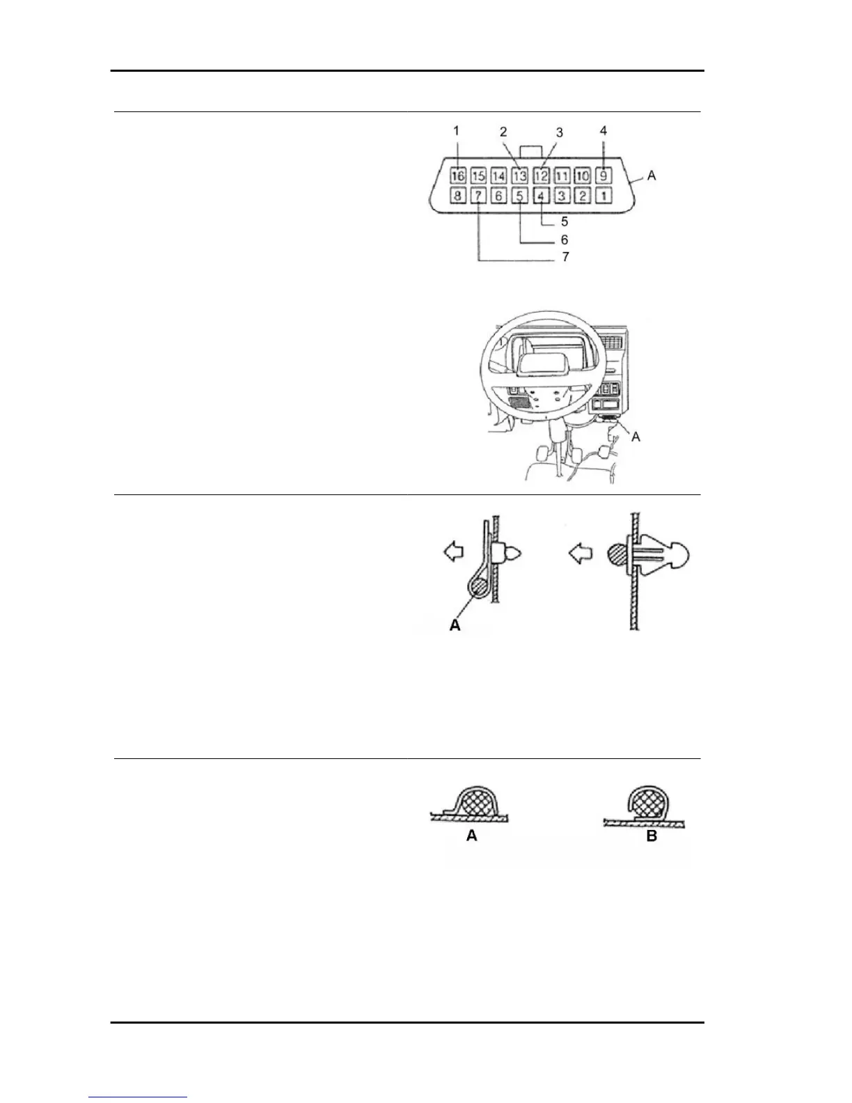
OBD DIAGNOSIS CONNECTOR TERMINALS:
A = OBD (DLC) Diagnosis connector
1. (+B) Battery positive (Voltage always detec-
ted: 9 ÷ 14V)
2. ECU-T
3. EFI-T
4. (REV) Engine rpm signal
5. (-) Chassis ground (Resistance < 10 Ω, al-
ways detected ).
6. (- ECU) Electronic control unit ground
7. (K line) OBD serial data line (generation of
pulses on the line during transmission.
GENERAL INSTRUCTIONS FOR MAINTE-
NANCE OPERATIONS ON THE CABLE HAR-
NESS
1. Do not pull or press connectors during the trans-
port or fitting of the electrical cable harness. To
prevent possible malfunctions.
2. Do not scratch or cut the cable harness during
transport or fitting.
3. Cable harness fixing system: if there are resin
clamps, make sure that the flaps of the fixing clip
are properly inserted into the chassis hole.
- Make sure that the fixing clip does not come out
of its hole by pulling it gradually in the arrow direc-
tion.
- If there are metal clamps welded to the chassis,
make sure to fit the cable harness so that it does
not make contact with the welded metal surface or
with sharp edges to prevent possible malfunctions.
(A) Correct
(B) Incorrect
General guidelines PORTER 1.3 16V
N GEN - 16

 Loading...