5. Remove the gear control fork shaft of the 1st
and 2nd gear and, gradually, the gear control fork
shaft of the 3rd and 4th gear, following the proce-
dure described in previous points from 1 to 3.
- CHECK THE REVERSE GEAR CONTROL LEVER MOVE-
MENTS OF THE REVERSE GEAR CONTROL LEVER AND
THE CONTACT WIDTH BETWEEN THE GEAR CONTROL
FORK AND THE RIBBED SLEEVE.
- BEFORE REMOVING THE GEAR CONTROL FORK,
PLACE THE RELEVANT GEARS IN NEUTRAL.
- DURING PIN REMOVAL, MEASURE THE TRACTION
FORCE OF THE SPRING.
Main and transmission shafts
Removal
Removing the input and the secondary shaft
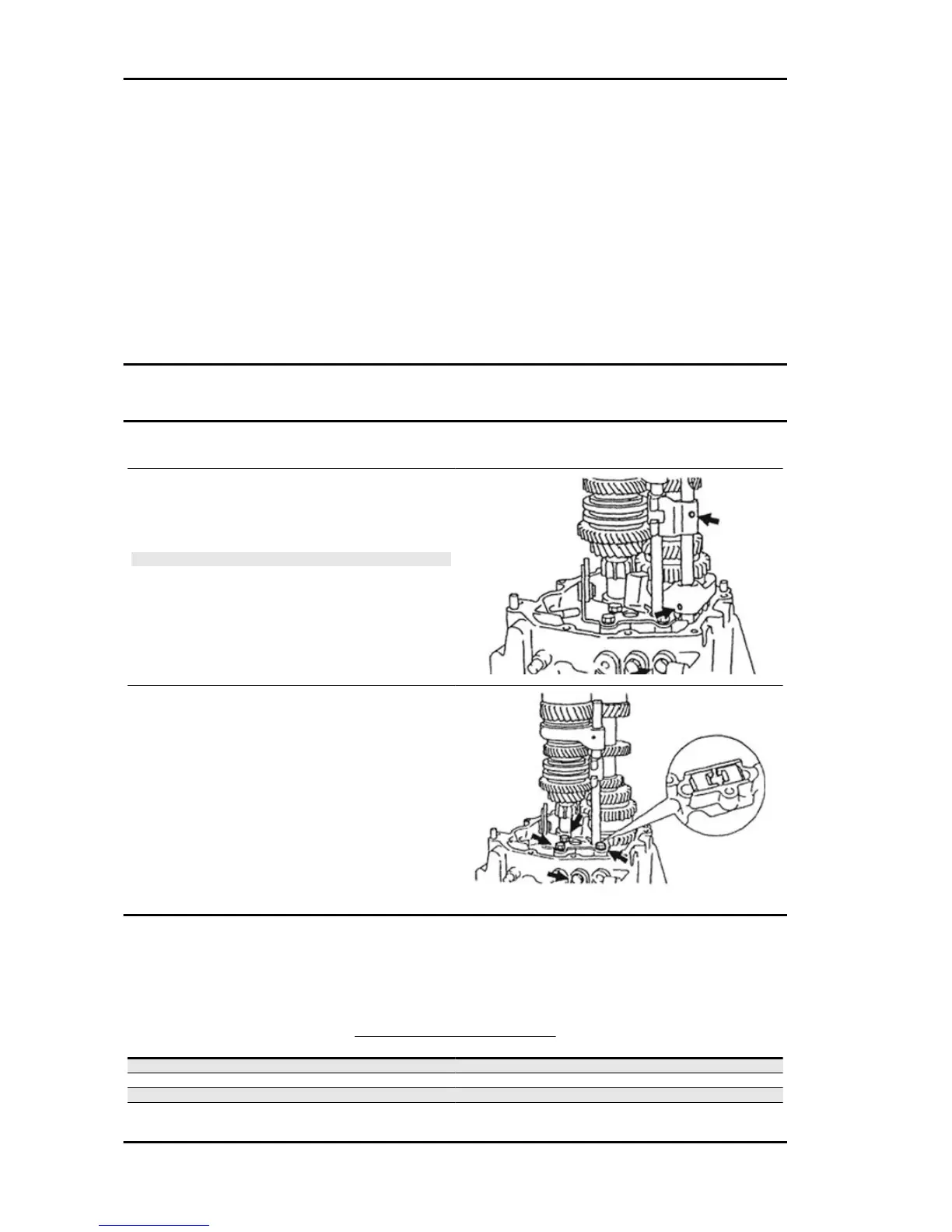
1. Take out the main shaft assembly with the nee-
dle bearing and the synchroniser ring.
N.B.
- MAKE SURE THAT EACH GEAR CAN BE PROPERLY.
2. Remove the reverse gear control lever, remov-
ing the three bolts.
3. Remove the plate locking the input shaft, by
taking out the three bolts.
4. While the input and the secondary shaft are held
with the hands, slide them off upwards.
Inspection
1. Measure the unloaded compression spring length for the gear control fork shafts and for the reverse
gear limit pin
SPRING SPECIFICATIONS
Specification
Desc./Quantity
Unloaded length for gear control fork shafts 40 mm
Fitting load (N) for gear control fork shafts 47.33 N
Fitting height for gear control fork shafts 30 mm
Unloaded length for reverse gear limit pin 24 mm
Gear-box PORTER 1.3 16V
GE - 560
 Loading...