Unit Terminal Condition Standard voltage or
resistance
Solutions
Fuel supply 2 - 62 Always Battery voltage Check the fuse
11-62 43-62 Ignition switch set to "ON" Battery voltage Check the main relay
Earthing unit 20 52 62 Always Less or equal to 1 Check the cable har-
ness ground
Camshaft sen-
sor
21 -53 Run the engine with the starter
motor
0.1 - 0.3 V (AC scale) Check the camshaft
sensor and the cable
harness
Ignition coil
control
62-29 62-64 Ignition switch set to "ON" Less or equal to 3 V Check the control unit
Once the inspection has finished:
1. Disconnect the ground lead terminal to the battery negative (-) pole.
2. Remove the special tool, disconnecting the relevant connectors from the control unit and engine
cable harness connectors.
3. Connect the cable harness connectors to the control unit.
4. Reconnect the ground lead terminal to the battery negative (-) pole.
- IF THE VOLTAGE OR RESISTANCE MEASURED DOES NOT COMPLY WITH SPECIFICATIONS,
CHECK THE CABLE HARNESS.
- IF THE PROBLEM IS NOT SOLVED BY REPAIRING THE CABLE HARNESS OR THE COMPO-
NENTS, REPLACE THE ELECTRONIC INJECTION CONTROL UNIT.
Riscaldamento e ventilazione
Fan check
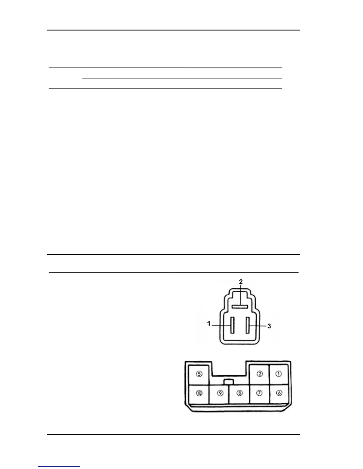
Fan check. Measure the resistance value between
following terminals.
Specified value:
1 - 3: ~ 2 Ohm
1 - 2: ~ 3 Ohm
Fan switch check
Make sure there is continuity between the respec-
tive terminals as indicated in the table.
Electrical system PORTER 1.3 16V
ES - 170

 Loading...