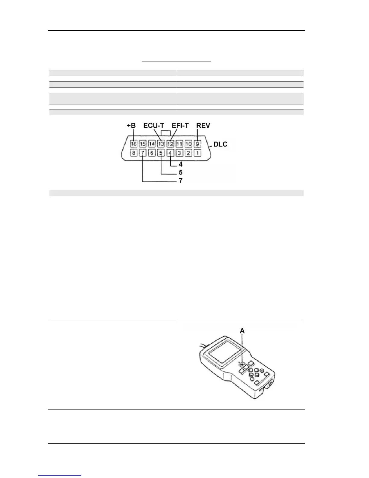
DLC CONNECTOR KEY
Specification Desc./Quantity
16 Battery powered
13 ECU - T
12 EFI - T
9 REV - Engine revs signal
7 OBD II serial data line (ISO 14230 K line)
Present during transmission
5 ECU ground
4 Chassis ground
N.B.
WITH THE CABLE OF THE DIAGNOSTIC TESTER DS-21 CONNECTED TO THE DATA LINK CON-
NECTOR BY MEANS OF THE CONTROL UNIT SELF-DIAGNOSIS CONTROL CABLE HARNESS,
SET THE IGNITION SWITCH TO ON. IF THE TESTER VOLTAGE INDICATOR DOES NOT TURN
ON, PERFORM THE FOLLOWING CHECKS AND REPAIR THE PARTS NOT WORKING PROPER-
LY.
Specific tooling
020618Y Cable harness for connecting the OBD Connector and the Diagnostic Tester
CONNECT THE TESTER DS-21 TO ANOTHER VEHICLE, SET THE IGNITION SWITCH TO ON:
1. When the voltage indicator of the diagnostic tester DS-21 turns on: Vehicle side operation failure.
Check the data link connector, +B and Ground. - BAT terminal voltage check - Continuity check
between terminals E and Ground.
2. When the voltage indicator of the diagnostic tester DS-21 does not turn on: Operation failure of the
diagnostic tester DS-21
A = voltage indicator (switch section)
Iniection System PORTER 1.3 16V
IS - 384

 Loading...