Home
PIAGGIO
Automobile
PORTER 1.3 16V 2008
PIAGGIO PORTER 1.3 16V 2008 User Manual
5
of 1
of 1 rating
892 pages
Give review
Manual
Specs
To Next Page
To Next Page
To Previous Page
To Previous Page
Loading...
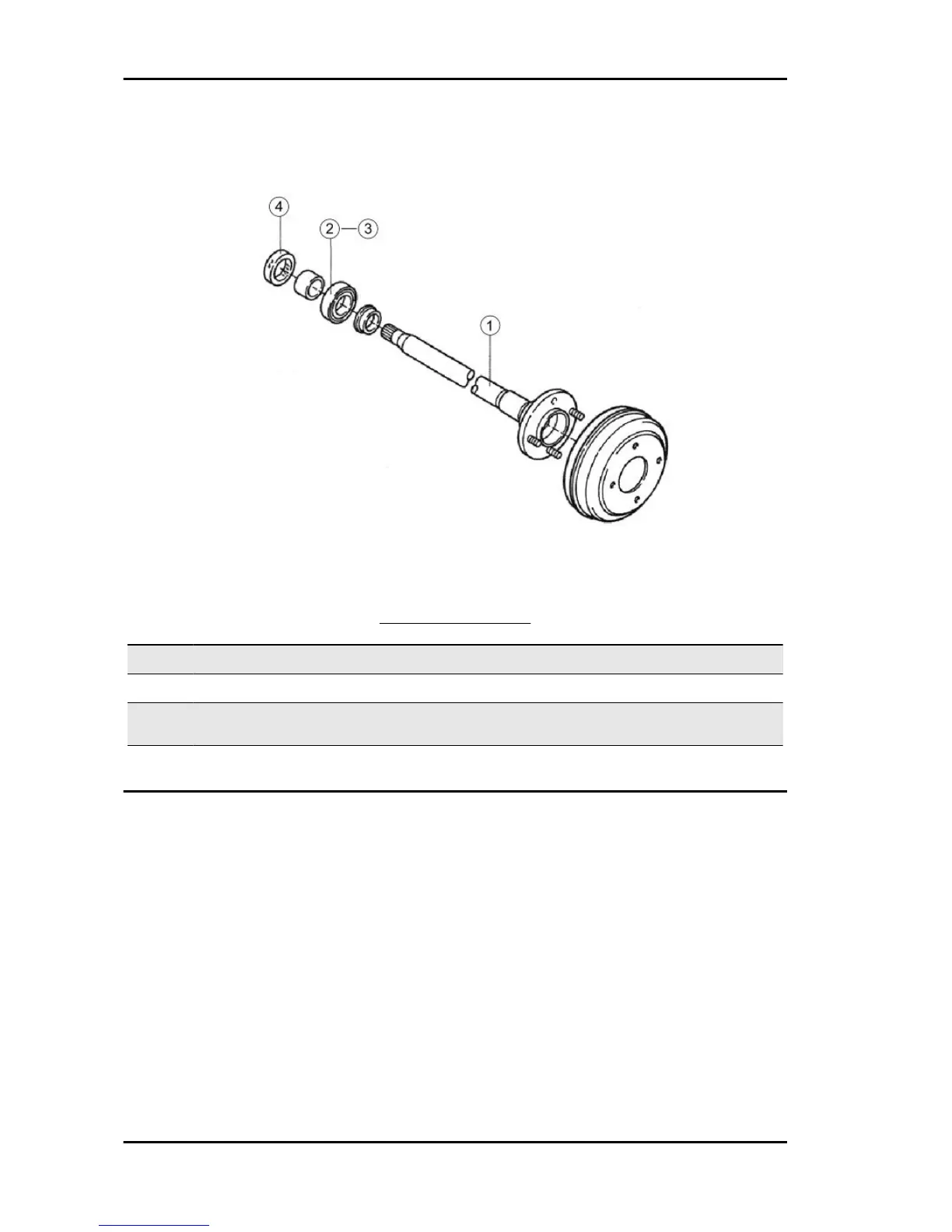
Rear half-shaft
REAR AXLE SHAFT
Code
Action
Duration
1
421051
REAR AXLE SHAFT (ONE SIDE) -
REPLACEMENT
2
421101
REAR AXLE SHAFT RADIAL BEAR-
ING (ONE SIDE) - REPLACEMENT
3
421201
REAR AXLE SHAFT RADIAL BEAR-
ING (BOTH SIDES) - REPLACE-
MENT
4
421301
SEALING RING («T» TYPE) - RE-
PLACEMENT
Time-sheet
PORTER 1.3 16V
TS - 872
871
873
Table of Contents
Index of Topics
5
General Guidelines
7
General Recommendations for Safety
8
Recommendations and Important Notes
8
General Guidelines
9
General Information
9
Safety Guidelines
10
Emergency Tow
11
Towing on a Flat Truck
11
Towing with Wheels Lifted
11
Front Support Point
12
Lifting Points
12
Rear Support Point
12
Description of Manual Use
13
Maintenance Guidelines
13
Support Points for Jack
13
Maintenance Procedure
14
Circuit Check
15
DLC Data Link Connector
15
Electric Fault Repair
15
General Instructions for Maintenance Operations on the Cable Harness
16
OBD Dignosis Connector Terminals
16
Fixing with Screws
17
Terminals and Connectors
17
Cable Harness
18
Disconnection of Connectors with Safety Lock
18
Using Resin Clamps
18
Disconnection of Terminal with Metal Lock
19
Terminal Insertion
19
Characteristics
21
Chassis Identification
22
Engine Identification
22
Engine Number and Type
22
Manufacturer Label
22
Pick-Up Model Bodywork Colour Codes
23
Van Model Bodywork Colour Code
23
Vehicle Model Code
23
Kinematic Chain Specifications
24
Impianto Elettrico
25
Dimensions
26
Table of Contents
27
Tightening Torques
27
Cylinder-Piston Oversizes
29
Vehicle Overhaul Data
29
Crankshaft - Rod Head
30
Piston - Pin
30
Piston Ring Oversizes
30
Camshaft
31
Tappets
31
Valve Clearance
31
Valve Guide - Valve Stem
31
Valve Spring
31
Crankshaft Pulley
32
Cylinder Head
32
Special Tools
33
Injection System Tool
34
Tooling
34
Engine Tool
35
Clutch Tool
36
Transmission Tool
36
Differential Tool
37
Brake Tool
38
Front Suspension Tool
38
Rear Suspension Tool
39
Steering Tool
40
Maintenance
42
Scheduled Maintenance Chart
43
Air Filter
44
Engine Assembly
44
Suggested Products Chart
44
Engine Oil Level Check
45
Engine Oil Replacement
45
Oil Quality Check
45
Engine Oil Change and Filter Replacement
46
Gear-Box Oil Replacement
46
Gearbox Oil Change
46
Leaks
46
Differential Oil Change
47
Differential Oil Replacement
47
Oil Leak
47
Coolant Change
48
Coolant Replacement
48
Cable Check
50
Spark Plug
50
Spark Plug Check
50
Headlight Alignment Check
51
Light Beam Direction Adjustment
51
Settings and Adjustments
51
Emission Control System
53
Component Layout
54
Catalytic Converter
55
Fuel Vapour Control System
56
Control System Diagram
57
Engine off
57
Engine Operation with the Accelerator Pedal Pushed
57
Blow-By Ventilation Pipe
58
Fuel Closing Device During Deceleration
58
Fuel Vapour Control Device
59
Emission Control Device
62
CO/HC Concentration Check
63
Exhaust Emission Control System
63
Troubleshooting
65
Engine
66
Clutch
67
Brakes
68
Gearbox
68
Suspensions and Steering
69
Electrical System
71
Battery-Chassis Ground
72
Ground Points
72
Main Ground
73
Rear Services System Ground
73
Services System Ground
73
Additional Ground
74
Electric Circuit Diagram
74
Injection System - Engine Ground
74
Electric Diagrams
78
Ignition
78
Starting and Recharging
79
Air Conditioning Electrical System Diagram
81
Colour Table
83
Fuse Box
83
Fuses
83
Instructions to Replace Fuses and Fuse Holders
83
Remote Controls
84
Air Conditioning Remote Controls
85
Electrical Controls
85
Multifunction Switch Lever
85
Ignition Key Switch
86
Rear Windscreen Wiper and Spray Nozzle Switch
88
Wiper Switch
88
Handbrake Switch
89
Headlamp Light Beam Adjustment Switch
89
Heated Rear Window Switch
89
Front Fog Light
90
Windscreen Wiper Mechanism
91
Windscreen Wiper Remote Control
92
Rear Wiper Mechanism
94
Start-Up System
95
Starter Motor
95
Inspection with Starter Motor Fitted
96
Bench Tests
98
Thrust Test
98
Checking Performance Without Load Applied
99
Pinion Engagement Upholding Test
99
Pinion Return Check
99
Starter Motor Removal
100
Commutator Check
103
Commutator Continuity Check
103
Rotor Insulation Check
103
Brush Check
105
Field Winding Check
105
Brush Holder Check
106
Brush Replacement Procedure
106
Coupling Check
106
Magnetic Field Check
107
Starter Motor Coupling Check
107
Bearing Check
108
Alternator
111
Recharge System
111
Rotor Check
117
Brush and Brush Holder
118
Stator
118
Brush Replacement
119
Rectifier Check
120
Rear Bearing Check
121
Rear Bearing Replacement
121
Front Bearing Check
122
Front Bearing Replacement
122
Refitting
123
Generator Shaft Fixing
125
Central Locking with Remote Control System Description
126
Power Lock
126
Electromechanical Actuators
127
Remote Control
127
Technical Characteristics of the System
127
New Remote Control Detection
129
Remote Control
131
System Maintenance
131
Alarm System and Central Locking
132
Electrical Contacts for Sliding Doors
132
System Protection Fuse
132
Operation Description
133
Garage Function
135
LED Warning
135
Alarm and Central Locking
136
Electrical Connections
136
Ultrasound Module Connection and Positioning
137
Super-High Frequency Module Connection and Positioning
138
Super-High Frequency Sensor Adjustment
139
Programmable Functions
140
Anti-Hijack Function
143
New Control Device Detection
145
New Pin-Code Programming
146
Emergency Unlocking through Pin-Code
147
Device Battery Replacement
148
Magnetic Contact
148
Infrared Sensor
149
Radio Control
149
Light Layout and Specifications
150
Replacing Light Bulbs
150
Bulb Position and Characteristics
151
Replacing the Headlight Bulbs
152
Front Indicators
154
Replacing the Front Turn Signal Light Bulbs
154
Replacing the Taillight Bulbs
154
Cab Rear Light
155
Rear Turn Indicators/Stop Lights
155
Replacing the Courtesy Lamp
155
Replacing the License Plate Light Bulb
155
Fog Light Headlamp Replacement
156
Fog Light Headlamps
156
Indicators - Warning Lights
157
Rear Fog Light
157
Reverse Gear Light
157
Instrument Panel
158
Speedometer
158
Fuel Gauge
160
Fuel Level Probe
161
Unit Check
161
Fuel Gauge and Temperature Gauge
162
Water Temperature Gauge
162
Ignition Check
163
Electrode Gap
164
Battery Voltage
165
Electrical Power Supply
165
Ignition Cable
165
Camshaft Sensor
166
Ignition Timing
167
Electronic Injection Control Unit
168
Control Unit Output Characteristics
169
Fan Check
170
Fan Switch Check
170
Internal/External Air Control Cable
171
Main Fitting Operations
171
Temperature Adjustment Cable
171
Flow Regulation Cable
172
Heating System and Ventilation
172
Cooling Circuit
174
Cooling Electric Fan Check
174
Engine Injection Cable Harness
175
Ignition Coil
176
Battery Negative Cable Harness
178
Engine - Chassis Ground Cable Harness
179
Battery Positive Cable Harness
180
Bodywork-Engine Ground Transmission Cable Harness
183
Cab Roof Cable Harness
184
Positions of Cables in the Connectors
184
Roof Light Cable Harness
185
Tail Door Cable Harness No.1
186
Engine Cable Harness
187
Rear Chassis Cable Harness
188
Instrument Panel Cables
190
Right Hand Drive Instrument Panel
190
Left Hand Instrument Panel
199
Right Hand Drive Van
207
Left Hand Drive Van
214
Tipper
222
E.G.R. Circuit Intake Duct
225
Engine Mechanism
225
Engine Type 2
225
Inlet Manifold Removal
225
Inlet Manifold - Fuel Delivery Pipe
227
EGR Valve - EGR Pipe
228
Exhaust Manifold Removal
230
Exhaust Pipe
230
Manifold Check
230
Exhaust Manifold Fitting
231
Alternator Drive Belt
232
Tension Adjustment
232
Cylinder Head - Exhaust Manifold
232
Driving Belt Test
233
Crown Gear Replacement
234
Flywheel Test
234
Crankshaft Pinion Fitting
235
Crankshaft Pulley Flange Fitting
235
Crankshaft Pulley Test
235
Driving Pulley
235
Crankshaft - Crankshaft Belt Pulley
235
Initial Operations
236
Timing Belt and Gears
236
Timing Belt Replacement
236
Timing Belt Removal
237
Belt Tensioner
240
Belt Tensioner Pulley Check
240
Crankshaft Pulley and Flange Test
240
Timing Belt Tensioner Spring Check
240
Crankshaft Pulley Removal
241
Crankshaft Pulley Fitting
242
Refitting Pulley on Crankshaft
242
Crankshaft - Timing System Pulley Screw
242
Camshaft Pulley Removal
243
Removal - Refitting Timing Pulley
243
Camshaft Pulley Fitting
244
Tension Spring Connection
244
Timing Belt Fitting
244
Timing System Belt Tensioner
246
Timing Belt Cover Screw
247
Valve Timing - Belt Tensioning
247
Crankshaft Pulley - Transmission Screws
248
Oil Pump Removal
248
Timing Side Oil Sealing Ring Replacement
252
Cover - Oil Pump
253
Cylinder Head Assembly
254
Cylinder Head Unit
254
Alternator Removal
256
Removal of the Engine Wire from the Cylinder Head
256
Head Removal
257
Cylinder Head Cover Inspection
260
EGR Valve Check
260
Pressure Relief Valve
260
Tappet Cover Gasket
260
Valve Clearance Adjustment
261
Rocking Lever and Pin Check
262
Tappet Pin
262
Rocking Lever Identification
263
Camshaft Check
264
Camshaft Inspections
264
Spacer and Crinkle Washer Check
264
Cylinder Head - M 8 Camshaft
266
Camshaft Axial Clearance Test
267
Head Removal - Cylinders
268
Gasket Residue Removal
269
Head Cleaning and Check
269
Combustion Chamber Cleaning
270
Levelness Tolerance
270
Head Cracking Check
271
Valve Check and Rectification
271
Valve Guide Bushing Cleaning
271
Checking Clearance between the Valve Guide and the Valve Stem
273
Valve Spring Check
274
Valve Guide Replacement
275
Valve Guides and Seats
275
Inlet Valve Guide
276
Specific Tooling
276
Checking and Cleaning the Valve Seats
277
Valve Seat Rectification
278
Fitting New Valves
280
Valve Manual Grinding
280
Head Fitting
281
Fitting the Valve Spring Seats on the Head
282
Valve Fitting
283
Valve Sealing Ring Fitting
283
Fitting the Valve Springs, Caps and Cotters
284
Cylinder Head - Water Temperature Sensor 24.5 ÷
285
Camshaft and Rocking Lever Pin Fitting
286
Cylinder Head - Cylinder Block
286
Final Operations
288
Oil Pump Fitting
253
Cylinder Head - Cylinder Head Cover
288
Base - Pistons - Cylinders
289
Block Removal
290
Operations on Components
290
Cylinder Block Removal
291
Oil Sump Removal
295
Piston Removal
296
Remove the Flywheel
297
Oil Sump Test
298
Piston - Removal and Inspection
298
Piston and Connecting Rod Test
298
Removing the Oil Sump
298
Piston and Connecting Rod Removal
299
Piston Inspection
300
Piston Ring Clearance
301
Piston Ring Opening
302
Piston Ring Rated Thickness
302
Piston Ring Removal
302
Piston Rings - Inspection
302
Piston and Connecting Rod Fitting
303
Piston Refitting
303
Connecting Rod Check
304
Pin-Connecting Rod Forced Coupling Check
304
Clearance Measurement between Connecting Rod Bushings and Crankshaft
305
Connecting Rod Clearance Measurement
305
Connecting Rod - Connecting Rod Cap
307
Connecting Rod Head Types
308
Connecting Rod Replacement
309
Cylinder Block Test
310
Cylinders
310
Cylinder Reaming
311
Cylinder Scale Removal
311
Cylinder Block Replacement
312
Crankcase Bearings
314
Oil Sealing Rear Gasket Replacement
314
Check the Axial Clearance of the Crankshaft
315
Checking Coupling Clearance of the Main Bushing
315
Crankshaft
315
Cylinder Block - Main Bearing Cap
317
Main Bushing Category Selection
318
Crankshaft Replacement
319
Connecting Rod Pin Category
320
Main Journal Categories
320
Connecting Rod Bushing Categories
321
Connecting Rod Head Categories
321
Water Pump Fitting
321
Cylinder Block - Water Pump
322
Oil Filter Fitting
322
Pressure Switch Fitting
323
Spring Connection to the Timing Belt Tensioner
323
Water Filler Fitting
323
Fitting the Clutch Disc and Driven Plate
324
Flywheel Fitting
324
Water Pipe Fitting
324
Cylinder Block Fitting
326
Fitting the Flange Supporting the Flywheel Side Sealing Ring
326
Rear Plate Fitting
327
Crankshaft Fitting
328
Arrangement to Fit the Head on the Engine
329
Fitting the Timing Pinion Fixing Screw
332
Fitting the Thermostat in the Cylinder Block
336
Oil Suction System Fitting
336
Oil Sump - Cylinder Block
336
Oil Sump Fitting
336
Checking and Adjusting the Ignition Timing
337
Compression Check
338
Idle Speed Check and Adjustment
339
Clutch Bell and Diaphragm Spring
343
Clutch Disc
344
Clutch Lever Stop
344
Spring
344
Thrust Bearing
345
Thrust Bearing Hub Stop
345
Clutch Cable
346
Clutch Pedal Adjustment
347
Free and Residual Travel of the Pedal
348
Lubrication System
348
Oil Pressure Check
349
Oil Pump
349
Connecting Rod Bearing Thickness Selection
307
Oil Pressure Switch - Cylinder Block
350
Measuring Pump Housing Clearance, Upper Part and Side Clearance
352
Wear Check
353
Oil Pump - Cylinder Block
355
Oil Filter - Cylinder Block
356
Checks
357
Oil Cartridge
358
Oil Pressure Warning Light
359
Coolant Pump
360
Cooling System
360
Oil Pump - Oil Pressure Switch
360
Fuel Filter
361
Fuel Filter Replacement
361
Injection Fuel System
361
Water Pump Pulley Test
361
Conceptual Diagram
362
Cooling System Diagram
362
Fuel Filter Fixing Nut
362
Radiator Cap Check
363
Radiator Cleaning
363
Cooling Circuit Check for Possible Water Leaks
364
Thermostat Inspection
365
Thermostat Removal
365
Thermostatic Valve
365
Cover - Thermostat 5.9 ÷
366
Thermostat Fitting
366
Radiator Removal
367
Radiator Fitting
369
Coolant Temperature Sensor
370
Radiator Thermoswitch Inspection
370
Radiator Thermoswitch Removal
370
Radiator Thermoswitch Specifications
370
Radiator Thermoswitch Fitting
371
Water Pump Removal
372
Inspecting Parts Relating to the Water Pump
373
Water Pump Sealing Test
374
Injection System
377
General Safety Measures
378
Injection System Circuit Check
379
Instructions for the Mobile Communication System
379
Using the Engine Checking System
381
DLC Connector Key
384
Component Location
385
Injection System Basic Diagram
386
ECU-Draco Connector Layout
387
Draco-Denso ECU Interface Diagram
388
EFI-Draco ECU Interface Diagram
388
Safety Measures to Repair the Supply System
397
Clip Position
398
Fuel Pipe
398
Pipe Insertion Length
398
Suction Pipe
398
Bleeding Pipe
399
Fuel Leak Check
400
European on Board Diagnostic System of Vehicles
401
ISO Diagnosis Code Key
402
Data Link Connector
404
Checking, Storing and Clearing the Failure Code/Frozen Image Data
406
Malfunction Phenomenon Reproduction Confirmation
406
Question Form
406
Counterchecking, Storing and Clearing Failure Code/Frozen Image Data
407
Visual Check
407
Connector/Cables
408
Final Confirmation Test
408
Malfunction Reproduction Simulation Test
408
Vibration
408
Another
409
Cold/Hot
409
Parts, Sensors
409
Water Application
409
Checking Diagram Common Options
410
Checking Wires and Connectors
410
Continuity Check
411
Resistance Check
411
Short Circuit
411
Visual Inspection and Contact Pressure Check
412
Check the Malfunction
413
Checking and Replacing the Electronic Control Unit
413
Failure Code Diagram Specifications
414
Specified Codes of the ISO/SAE Standards
414
Daihatsu Motor Corporation Codes
418
Failure-Free Function
419
Failure-Free Specifications
419
Matrix Table for Troubleshooting
420
Start-Up Problems
420
Engine Does Not Hold Idling
421
Engine Irregular Performance
421
Diagnostic Failure Code Check
422
Diagnostic Failure Code Clearing
422
Engine Poor at Full Power
422
Signs of Knocking
422
Failure Code Check Using the Diagnostic Tester
423
Warning Light Check
423
The Diagnostic Tester DS-21 Is Not Used
425
Using the Diagnostic Tester DS-21/OBD II General Scanning Device
425
Diagram of Basic Operations to Check the Engine
426
Ignition Timing Check
427
Engine Idle Speed Check
428
Fuel Pressure Check
428
Fuel Injector Operation Confirmation
430
Spark Check
430
Scanning Device Data
431
Service of the Electronic Control Unit and Relevant Circuits
433
Wiring Diagram - Inlet Manifold Absolute Pressure Circuit
436
Absolute Pressure in the Inlet Manifold
438
Checking Procedure
438
Circuit Description
438
Diagnostic Failure Code Detection Conditions
438
Ground Node
444
IAT Sensor Circuit Description
445
Using Diagnostic Tester DS-21/Digitek/Obd II General Scanning Device
446
Diagnosis with Multimeter and Interface Wiring
449
Does the Value Measured Match that One Specified?
450
Does the Value Measured Match the One Specified?
450
Is the Voltage Measured 5.0 V?
450
Using the Tester DS-21 or OBD II General Scanning Device
451
Functional Check
467
Using the Diagnostic Tester DS-21 or OBD II General Scanning Device
482
Confirming the Driving Configuration
486
Signal Control
492
Using the Diagnostic Tester DS-21
500
Without Using the Diagnostic Tester DS-21
503
Ignition Switch
533
Intake Air Temperature Sensor
539
Vacuum Switchover Valve for Bleeding Fuel Evaporative Emissions
540
Throttle Valve Sensor
541
Vacuum Switchover Valve for Increasing Idle Speed
541
Engine Coolant Temperature Sensor
542
VSV EGR - Vacuum Switchover Valve for EGR
542
Fuel Pump
543
Main Relay and Fuel Pump Relay
543
Front and Rear Oxygen Sensors with Heater
544
Ignition Unit
544
Terminal Resistance Values
544
Gear-Box
545
For Removing and Fitting the Conical Spring Washer
546
Gearbox and Cover
548
Components
549
Sub-Gear
549
Clutch Cover
550
Recommendations before Removal
557
Repairs to be Carried out on the Vehicle
557
Remove the Gearbox Cover
559
Removing the Gear Control Fork
559
Removing the Gearbox
559
Inspection
560
Main and Transmission Shafts
560
Removing the Input and the Secondary Shaft
560
Spring Specifications
560
Forks and Heads of the Gear
561
Gear Clutch Control
561
"S" Type Oil Seal Replacement
562
Reverse Transmission Gear
562
Bimetallic Bushing
563
Replacement of Gearshift Lever and Gear Components
563
Inlet Shaft
564
3Rd and 5Th Gear
567
Fitting
571
Main Shaft
574
Transmission Shaft
577
Secondary Shaft Components
578
Replacing the Conical Spring Washer
583
Secondary Shaft - Inspection before Removal
586
Gear Fork Shafts
588
Fitting the Gear Control Fork and the Relevant Shaft
589
Fitting the Gear Assembly on the Vehicle
592
Differential
594
Differential Removal
596
Operations before Removal
597
Bearings
600
Control Pinion and Crown Gear
600
Differential Housing
600
Side Pinion Gear and Pinion
600
Coupling Flange
601
Adjustment Procedure
602
Adjusting Control Pinion Protrusion
603
Available Shim Washers
604
Bearing Preloading Measurement
605
Differential Housing Fitting
605
Adjusting Crown Gear Clearance and Bearing Preloading
606
Crown Gear
606
Checking/Adjusting Teeth Contact Surface between Crown Gear and Pinion
608
Cover Refitting
609
Braking System
610
Brake Pedal
611
Brake Pipe
611
Empty Travel
611
Inspection and Repair
612
Pedal Travel Adjustment
614
Adjusting the Reserve Travel of the Brake Pedal
615
Brake Fluid Reservoir
615
Pedal Height Adjustment
615
Specified Values
615
Brake Booster Inspection Procedure
618
Power Brake Hermetic Seal Check
618
Power Brake Multimeter Connection
619
Power Brake Operation Check
619
Power Brake Simple Check
619
Checking the Power Brake Hermetic Seal with Loaded/Unloaded Vehicle
620
Power Brake Operation Failure Check
620
Air Bleeding
621
Brake System
621
Filling with Brake Fluid
621
Brake Fluid Leakage Check
622
Front Disc Brake Pad
622
Front Disc Brake
624
Front Disc Brake Calliper
625
Disc Thickness and Irregular Wear
627
Pad Thickness and Irregular
627
Operation Following Installation
629
Rear Brake
629
Brake Drum Wear
631
Wear of Friction Material
631
Parking Brake Lever
634
Valve Timing - Belt Refitting
244
Handbrake
637
Parking Brake Cable
637
Operation before Removal
638
Fitting (Pickup Model)
639
Brake Controller Lspv
641
LSPV (Brake Calibrator)
641
Operation after Fitting
641
Performance Diagram
644
Pickup
645
Van
645
Component
647
LSPV Brake Calibrator
648
Lspv Assembly
651
LSPV Brake Calibrator - Bracket
652
Clearance Check
655
Inspection on Vehicle
655
Noise Check
655
Steering Column
659
Steering Arm
660
Universal Joint Arm
661
Steering Box Assembly
666
Strut Bracket Body
666
Control
670
Assembly Procedure of the Rack and the Steering Pinion
675
Steering Pinion Preloading
676
Rack Guide Protection Lock Nut - Steering Rack Housing
676
Steering Column
677
Key Switch Cylinder Removal
678
Tie-Rods
681
Arm Head
682
Checking after Fitting the Arm Heads
683
Toe-In
683
Front Wheel Alignment Check
684
Steering Angles
684
Pick up Front Wheel Alignment
685
Steering Wheel Clearance
685
Van Front Wheel Alignment
685
Toe-In Adjustment
687
Toe-In Measurement
687
Wheel Alignment
687
Suspensions
689
Axle and Front Suspension
690
Front
690
Shock-Absorbers Removal
691
Steering Articulation Fitting
692
Spring Removal
694
Front Arms Removal
695
Shock Absorber Operation Check
695
Suspension Lower Arm
695
Twisting and Breaking
698
Front Hubs Removal
699
Castle Nut - Front Axle Hub 177.0 ÷
701
Front Axle Bearing Installation
702
Front Axle Bearing Replacement
702
Preliminary Checks before the Wheel Alignment Check
703
Turning Radius Gauge Setting
705
Checking the Camber, Caster and Kingpin Angles
706
External Side Wheel Steering Angle Check
706
Wheel Steering Angle Correction
706
Axle and Rear Suspension
710
Wheel Hub
710
Brake Pipe Joint - Brake Cylinder
715
U-Bolt - Leaf Spring Buffer
718
Spring Support Pin - Leaf Spring Assembly
719
Rear Shock Absorber - Chassis (Upper Part)
721
Noise
722
Shock Absorbers
722
Tipper Version
724
Electric Diagram - Tipper
727
Tipper Removal
728
Tipper Refit
729
Hydraulic Jack Fitting
731
Hydraulic Jack Removal
731
Removal of Pump Parts
732
Removing Valve Body from the Electric Motor
733
Valve Body Removal
733
Valve Body Fitting
734
Assembly of Pump Parts
735
Fitting the Valve Body to the Electric Motor
735
Hydraulic Pump and Electric Motor Fitting
736
Pressure Relief Valve Check and Calibration
737
Chassis
739
Windscreen
740
Side Windows
742
Rear Window Upholstery Panel
744
Tools and Other Equipment
744
Doors
745
Door Alignment Adjustment
752
Prescribed Alignment Sizes
752
Sliding Door Frame
753
Sliding Door Upholstery Panel
753
Upholstery Panel Removal
755
Upper Roller Removal
763
Central Hinge Removal
764
Lower Roller Removal
764
Central Hinge Fitting
766
Lower Roller Fitting
766
Adjustment in Longitudinal Direction
767
Height Adjustment
767
Sliding Door
767
Adjustment of Height Difference
768
Adjustment Tolerance
768
Rear Door Upholstery Panel
770
Door Panel
772
Adjustment in Longitudinal Direction of the Upper Section
773
Front Bumper
773
Catalytic Converter Replacement
774
Replacing the Exhaust
774
Exhaust Pipe - Catalytic Converter
775
Light Unit
775
Front Panel Components
778
Removing Upper Panel of Instrument Panel and Glove Compartment
780
Instrument Panel Removal
781
Instrument Panel Installation
783
Removing Air Vents/Loudspeakers/Cigarette Lighter
783
Instrument Panel Support - Chassis
783
Refitting Air Vents/Loudspeakers/Cigarette Lighter
786
Starting Operations
787
Van Front Seat
789
Check-Up of Inclination Angle until Clicking Sound of Belt Is Heard
790
Fitting the Front Seat Internal Bolt
791
Safety Belt at Three Anchor Points with Winder
791
Safety Belts
791
Fuel Tank Cap
794
Pre-Delivery
795
Closing and Hinge Operation
797
General Inspection
797
Vehicle External Appearance
797
Vehicle General Check
797
Internal
798
Vehicle Cleaning
798
User Manual
799
Wheel Guard-Central Cover Fitting
799
Loosening the Hub Clamps
800
Nut Tightening
800
Preliminary Inspections
800
Tyre Pressure
800
Adjusting Devices
801
Cigarette Lighter
801
Seatbelt
801
Horn Functioning
802
Horn Operation
802
Windshield Washer Orientation Adjustment
802
Wipers Operation
802
External Lights
803
Headlamp Orientation
803
Headlight Adjustment
803
Windscreen Wiper and Washer Operation
803
Chassis Inspection
804
Checks to be Carried out under the Body
804
Warning Lights
804
Door Lock Adjustment
805
Door Stop Plate - Chassis
805
Battery Connections
806
Bellow Joint
806
Engine Housing Inspection
806
Ignition Timing
806
Sleeve Connections and Fluid Pipes
806
Coolant in the Expansion Tank
808
Window Cleaning Liquid
808
Windshield Washer Fluid in the Reserve Tank
808
Engine Idle
809
Idle Speed Adjustment
809
Rpm Indicator Connection
809
Brake Fluid
810
Brake Pedal Adjustment
810
Engine Oil
810
Service and Parking Brake Operation
810
Road Test
811
Steering Wheel
811
Test Drive
811
Steering - Wheel Hub Joint - Dust Guard
812
Time-Sheet
814
Camshaft and Timing Belt
815
Drive Shaft
816
Propeller Shaft
817
Leaf Spring and Shock Absorbers
819
Suspension Leaf Spring
819
Battery
820
H.T. Coil
821
HV Coil and Spark Plugs
821
Cable Harnesses
822
Front Chassis
824
Bodywork
825
Rear Chassis
825
Wheel Rim
826
Brake Cylinder
827
Horn
827
Clutch Assembly
828
Clutch Unit
828
Engine Unit
829
Ducts
830
Oil Sump
831
Rear Differential
832
Brake Discs
834
Fluid Leaks
805
Leakages
805
Brake Disc
836
Position Light
837
Sidelight
837
Headlamps
838
Oil Filter
840
Parking Brake
841
Brake Shoes and Drum
842
Drum Shoes
842
Front Grid
842
Front Grille
843
Fuel Injection
844
Inside Parts
845
Interiors
845
Switches and Regulators
846
Window Sprayer
847
Gear Stick
848
Windscreen Washers
848
Gearshift Lever
849
Single-Block
850
Rear Floor Panel
852
Dashboard
854
Bumper
856
Clutch Pedal
858
Column/ Steering/ Steering Housing/ Joints
860
Piston and Connecting Rod
860
Water Pump and Thermostat
861
Fuel Pump
862
Brake Fluid Pump
863
Rear Van Door
865
Tail Door
865
Rear-View Mirror Sun Shade
866
Radiator and Water Pipes
867
Radio
868
Heating
869
Front Seat
870
Rear Van Seat
871
Lights
838
Rear Axle Shaft
872
Cam Sensor
873
Fuel Tank and Pipes
874
Front Suspensions and Front Axle
876
Rear End-Gate
877
Tailboard
877
Spare Wheel Mounting Bracket
878
Spare Wheel Support
878
Labels
879
Plates
879
Windscreen Wiper
880
Rear Van Wiper
881
Head
882
Accelerator Transmision
883
Throttle Cable
883
Brake Hoses
884
Brake Pipes and Calibrator
884
Valves
885
Van Side Window
886
Windows
886
Door Glass and Profile
887
Frameless Side Window
887
Side Glass
887
Steering
889
Index
891
5
Based on 1 rating
Ask a question
Give review
Questions and Answers:
Need help?
Do you have a question about the PIAGGIO PORTER 1.3 16V 2008 and is the answer not in the manual?
Ask a question
PIAGGIO PORTER 1.3 16V 2008 Specifications
General
Brand
PIAGGIO
Model
PORTER 1.3 16V 2008
Category
Automobile
Language
English
Related product manuals
PIAGGIO Ape
144 pages
 Loading...