13. Fit the spark plugs. Tighten to the prescribed
torque.
14. Fit the ignition coil on the cylinder head cover.
15. Connect the ignition coil connector.
Locking torques (N*m)
Cylinder head - Spark plug 15 ÷ 22 Cylinder head
cover - Ignition coil 6÷11
Electrical power supply
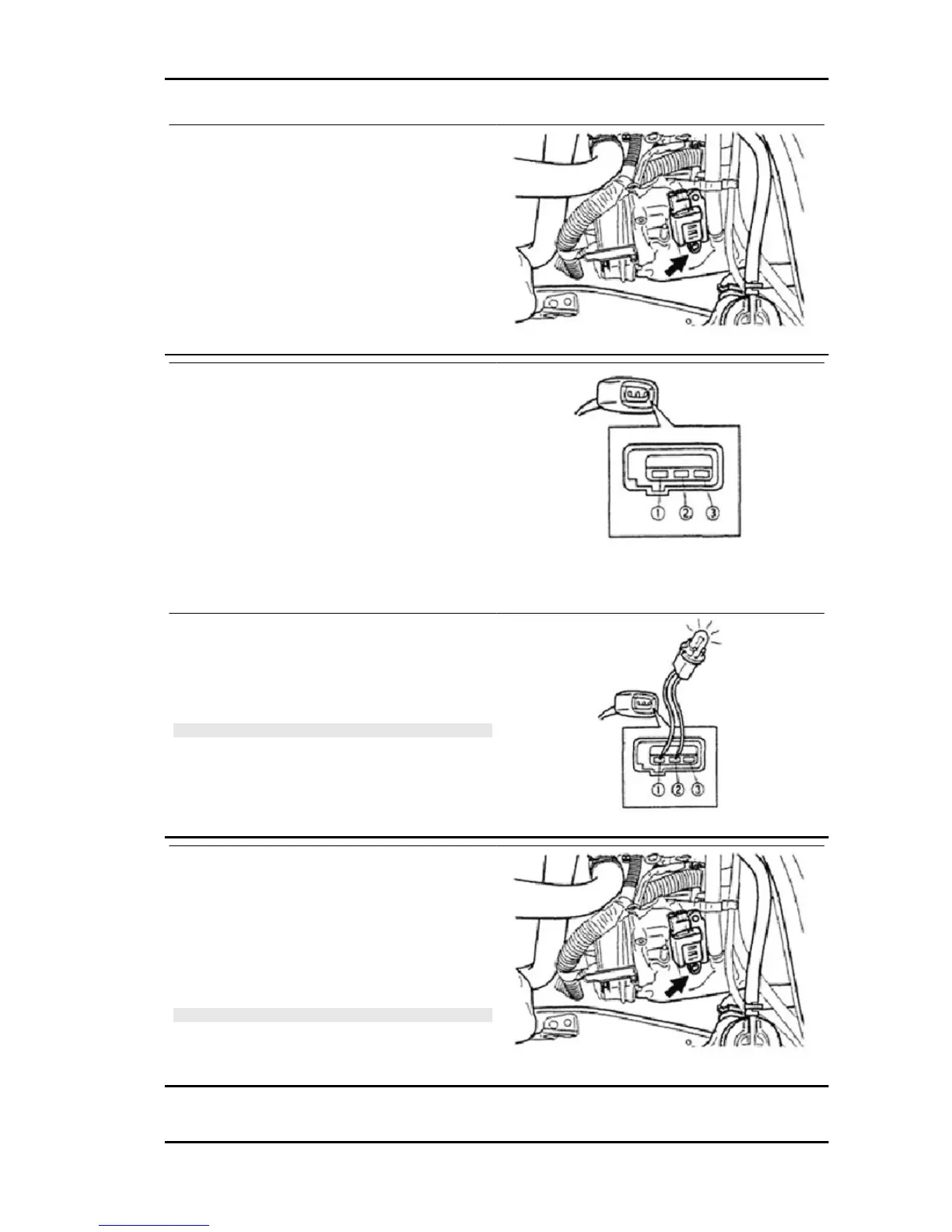
1. Disconnect the ignition coil connector.
2. Measure voltage between terminals 3 +B on the
wire connector side and with the ignition switch set
to ON.
- IF VOLTAGE DOES NOT COMPLY WITH THE SPECIFIED
VALUE, CHECK THE FUSE AND THE CABLE HARNESS.
Characteristic
Specified value:
Battery voltage
3. Connect the bulb (12 V/6 W) between terminals
S1 and GR on the wire connector side of the igni-
tion system. Check that the bulb turns on when the
engine is started with the starter motor.
N.B.
IN THESE CONDITIONS, THE BULB MUST START FLASH-
ING. OTHERWISE, CHECK THE SENSOR OUTPUT TERMI-
NAL OF THE CAMSHAFT SENSOR.
Ignition cable
1. Disconnect the ignition coil connector.
2. Remove the ignition coil by taking out the fixing
nuts.
3. Disconnect the spacer and the cable from the
spark plug.
N.B.
- REMOVE THE IGNITION CABLE FROM THE SPARK
PLUGS AND FROM THE IGNITION COIL HOLDING THE
RUBBER SHEATH.
PORTER 1.3 16V Electrical system
ES - 165

 Loading...