•
Check there are no interrupted or
short-circuited wires in the cable har-
ness and connector.
Vacuum switching valve connector XAB - terminal
56 VSV2. Repair and replace the cable harness or
the connector, if necessary.
5. Checking the vacuum switching valve to increase idle speed
Replace the vacuum switching valve to increase idle speed, if necessary.
6. Checking the input signal of the electronic control unit to verify the electric charge
•
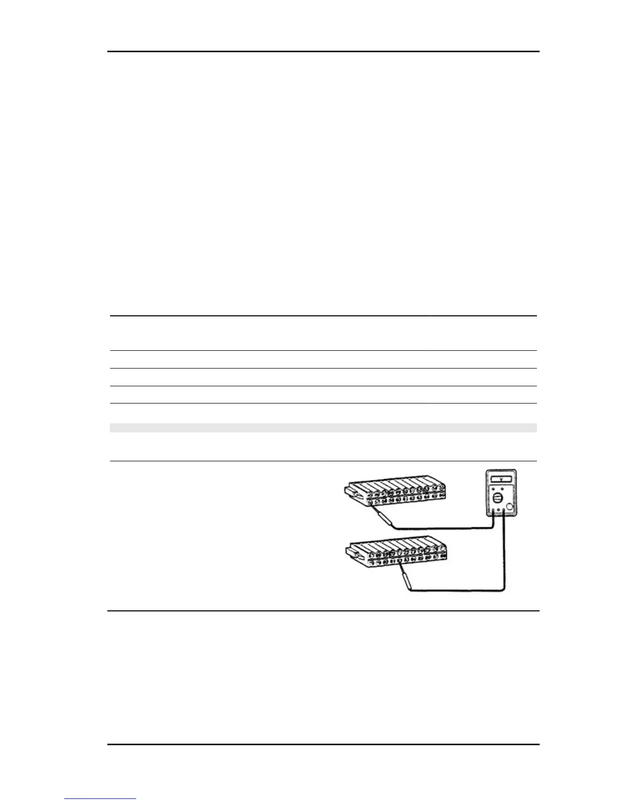
Set the special tool (sub-wiring harness).
•
With the engine running, measure voltage between terminals 56 and 82 VSV2 - and E2,
E01.
- Condition Specified value
1 Until the complete engine warm-up, after start-up with cold en-
gine
0.5 V or less
2 Anti-fog system switch set to ON 0.5 V or less
3 Heater fan switch set to ON 0.5 V or less
4 Front headlight switch set to ON 0.5 V or less
5 Cooling fan activated 0.5 V or less
N.B.
DO NOT PERFORM THE MEASUREMENT IF MANY CONDITIONS TAKE PLACE AT THE SAME
TIME.
If it does not match the specified value, check and
repair the relative systems, otherwise check the
malfunction that is detected intermittently and bad
contacts.
Controlli generali
(IAT) Intake air temperature sensor
1. Measure resistance between terminals.
PORTER 1.3 16V Iniection System
IS - 539
 Loading...