Fuel gauge
Unit check
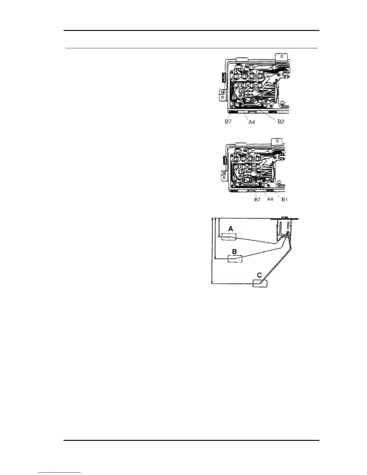
1. Remove the combined instrument panel.
2. Measure the resistance value between termi-
nals B7 and B2.
3. Connect the multiple pole connector to the
"combination meter".
4.Turn the key switch to ON.
5. Make sure that battery voltage is applied be-
tween terminal A4 and the body ground.
6. Make sure that a variable voltage between 2 and
7 V is applied between terminal B7 and the body
ground.
Fuel level probe
Remove the fuel tank. Then, remove the fuel level probe.
Check
Measure the resistance value between the terminal and the body to the positions listed below.
Float A position: Resistance 5-10 Ohm Reference dimensions 95.5 ± 3 mm
Float B position: Resistance 30-38 Ohm Reference dimensions 95.5 ± 3 mm
Float C position: Resistance 87-102 Ohm Reference dimensions 230 ± 3 mm
PORTER 1.3 16V Electrical system
ES - 161

 Loading...