CONNECTORS. CHECK VERY CAREFULLY THE CONNEC-
TORS OF THE SENSOR AND THE ACTUATOR
Short circuit:
this is caused by a short circuit between the cable
harness and the chassis ground, or by a short cir-
cuit inside the switches, etc.
- IF A SHORT CIRCUIT IS DETECTED BETWEEN THE CA-
BLE HARNESS AND THE CHASSIS GROUND, CHECK IF
THE WIRES ARE ENTANGLED, IF THE WIRE IS RUBBED,
IF THE INSULATING PART IS BROKEN ALLOWING A CON-
TACT WITH OTHER PARTS, AND IF THE WIRE IS LOCKED
PROPERLY.
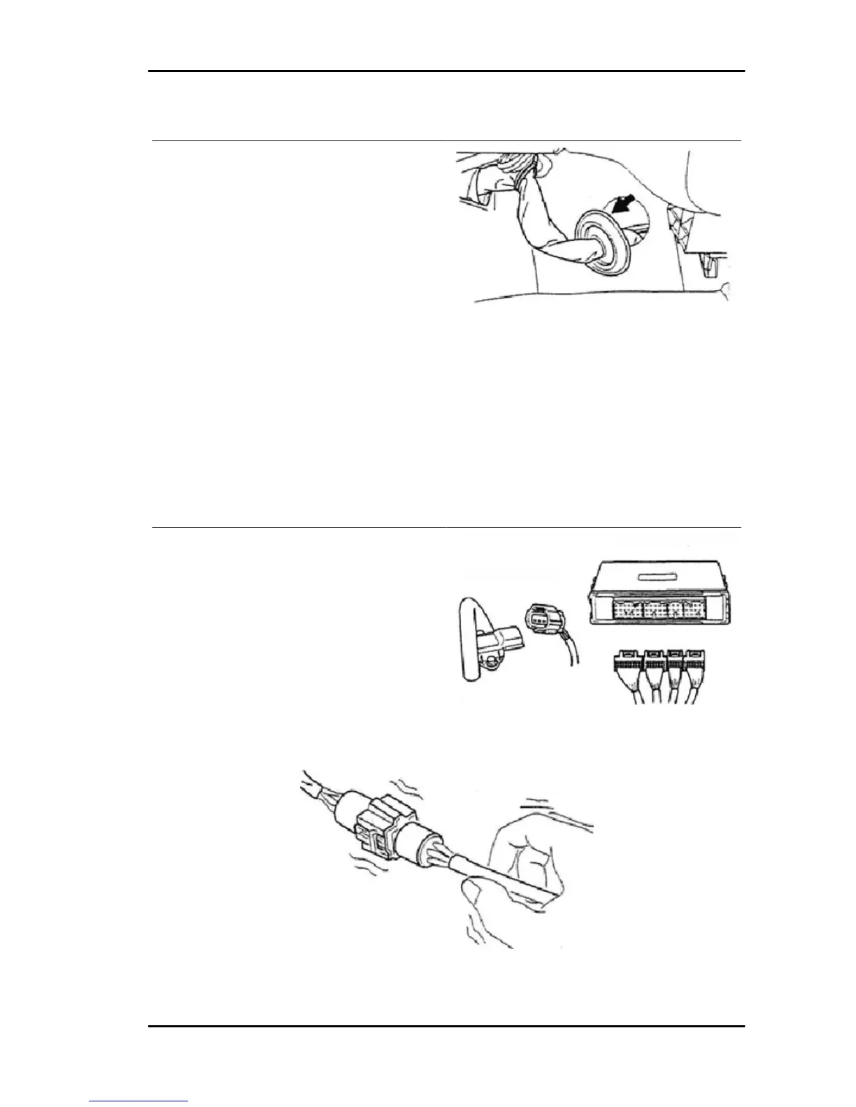
Resistance check (short circuit check)
1. Disconnect the connector on both sides
2. Measure the resistance between the relevant connector terminals and the chassis ground. Besides,
check connectors on both sides.
- SLIGHTLY SHAKE THE CABLE HARNESS LONGITUDINALLY AS WELL AS HORIZONTALLY
DURING THE MEASUREMENT OF RESISTANCE.
Characteristic
Resistance:
10 MΩ or more
Continuity check (interrupted wire check)
1. Disconnect the connector on both sides of the
electronic control unit and the sensor
2. Measure resistance between the connector ter-
minals
- SLIGHTLY SHAKE THE CABLE HARNESS LONGITUDI-
NALLY AS WELL AS HORIZONTALLY DURING THE MEAS-
UREMENT OF RESISTANCE.
Characteristic
Resistance:
10 Ω or less
PORTER 1.3 16V Iniection System
IS - 411

 Loading...