Operation check
Push the rear part of the vehicle with downward force in order to check the damping capacity of the
shock absorbers.
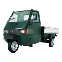
In the case that the wheel bearing is loose, check
the clearance in the axial direction, using the fol-
lowing tool and the micrometer.
Specific tooling
020222y Front hub and drum extractor
Characteristic
Front wheel bearings
Specified value
Maximum limit: Do not exceed 0.05 mm
PICK UP FRONT WHEEL ALIGNMENT
Specification Desc./Quantity
Camber angle 1°23' +40'-50'
Caster angle 3°13' ± 1°
Kingpin inclination angle 10°49' ± 1°
Toe-in 1 passenger: 2.0+1.5-1.0
Unloaded vehicle: 1.5+1.5-1.0
Steering angle Inside: 36°+0°-3°
Outside: 34.8°+0°-3°
VAN FRONT WHEEL ALIGNMENT
Specification
Desc./Quantity
Camber angle 1° +40'-50'
Caster angle 3°02' ± 1°
Kingpin inclination angle 11°25' ± 1°
Toe-in 1 passenger: 2.0+1.5-1.0
Unloaded vehicle: 1.5+1.5-1.0
Steering angle Inside: 36°+0°-3°
Outside: 34.8°+0°-3°
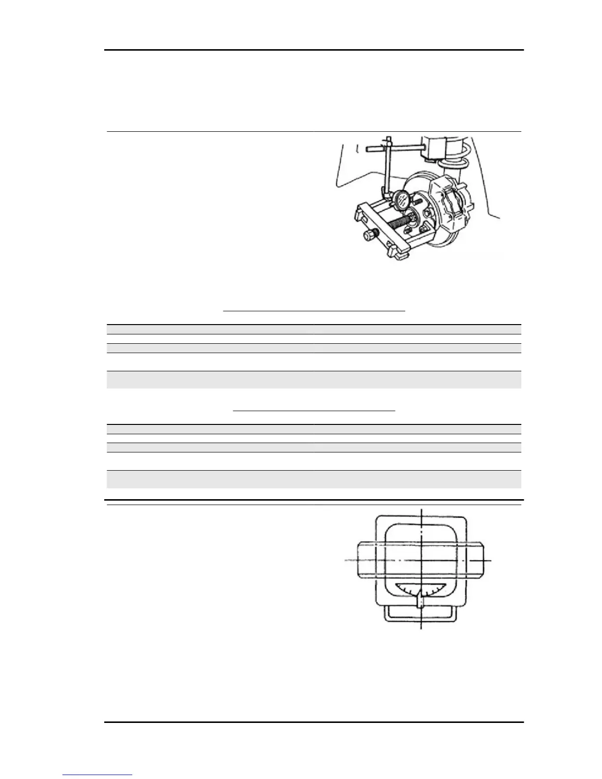
Turning radius gauge setting
•
Set the turning radius gauge to point
zero. Lock the indicator.
•
Place the vehicle so that the wheel/
flooring surface is aligned with the cen-
tre of the turning radius indicator.
- CARRY OUT THE CHECK ON LEVEL GROUND.
- IF A PORTABLE TURNING RADIUS GAUGE IS USED,
PLACE A PLATE WITH THE SAME THICKNESS AS THAT
OF THE INDICATOR UNDER THE REAR WHEEL IN ORDER
TO KEEP THE VEHICLE LEVEL.
- MAKE SURE THAT THE FRONT WHEELS ARE NOT
STEERED.
- KEEP THE VEHICLE UNLOADED. MAKE SURE THAT THE
BRAKE PEDAL IS ENGAGED, USING A BRAKE PEDAL
THRUSTING DEVICE, SO THAT THE VEHICLE DOES NOT
MOVE DURING CHECK.
PORTER 1.3 16V Suspensions
SS - 705
 Loading...