2. Connection of the specific tool.
•
Disconnect the ground lead from the
battery negative (-) pole.
N.B.
- THE ELECTRONIC INJECTION UNIT CAN BE CHECKED
BY MEASURING THE RESISTANCE OR VOLTAGE ON THE
PROBES OF HE SPECIAL TOOL.
CAUTION
- BEFORE DISCONNECTING THE GROUND LEAD CHECK
IF THE FAILURE CODES ARE STORED. CUT OFF POWER
SUPPLY AND DATA STORAGE IS CANCELLED.
•
Disconnect the cable harness connec-
tor from electronic injection control unit
connectors on located on the upper
side of the glove-box.
•
Connect the specific tool between ca-
ble harness connectors and control
unit connectors.
•
Reconnect the ground lead from the
battery negative (-) pole.
CAUTION
- BEFORE DISCONNECTING OR RECONNECTING THE
ELECTRONIC INJECTION ECU CONNECTORS, DISCON-
NECT THE GROUND LEAD FROM THE BATTERY NEGA-
TIVE (-) POLE WITH THE IGNITION SWITCH AND ALL THE
ACCESSORY SWITCHES SET TO "OFF".
- WHILE FITTING A NEW BATTERY, PAY ATTENTION NOT
TO INVERT POLARITY. AN INVERTED CONNECTION OF
POLES COULD DAMAGE THE CONTROL UNIT.
- BEFORE USING THE SPECIAL TOOL, CHECK WHETHER
ITS TERMINALS ARE SHORT CIRCUITED OR OPEN CIR-
CUIT.
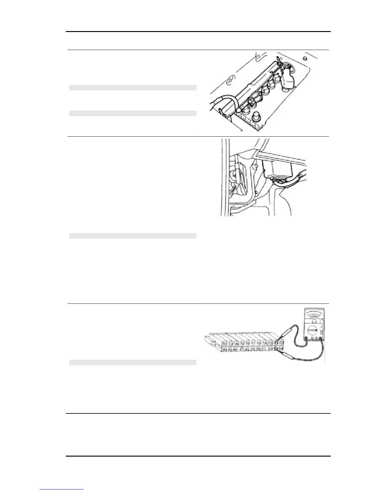
3. Voltage or resistance measurement.
•
Measure the voltage or resistance be-
tween each terminal.
•
Check that the measured voltage or re-
sistance comply with specifications.
N.B.
- BESIDES, IF THE CHECK DESCRIBED ABOVE DETER-
MINES THAT THE CONTROL UNIT SHOULD BE RE-
PLACED, MAKE SURE THAT THE CONTROL UNIT FAIL-
URE IS NOT DUE TO EXTERNAL FACTORS. AFTER-
WARDS, REPLACE THE CONTROL UNIT.
- VOLTAGE MEASURED WITH ALL CONNECTORS CON-
NECTED.
Control unit output characteristics
Control unit voltage or resistance standard values are indicated in the table.
PORTER 1.3 16V Electrical system
ES - 169

 Loading...