Circuit description
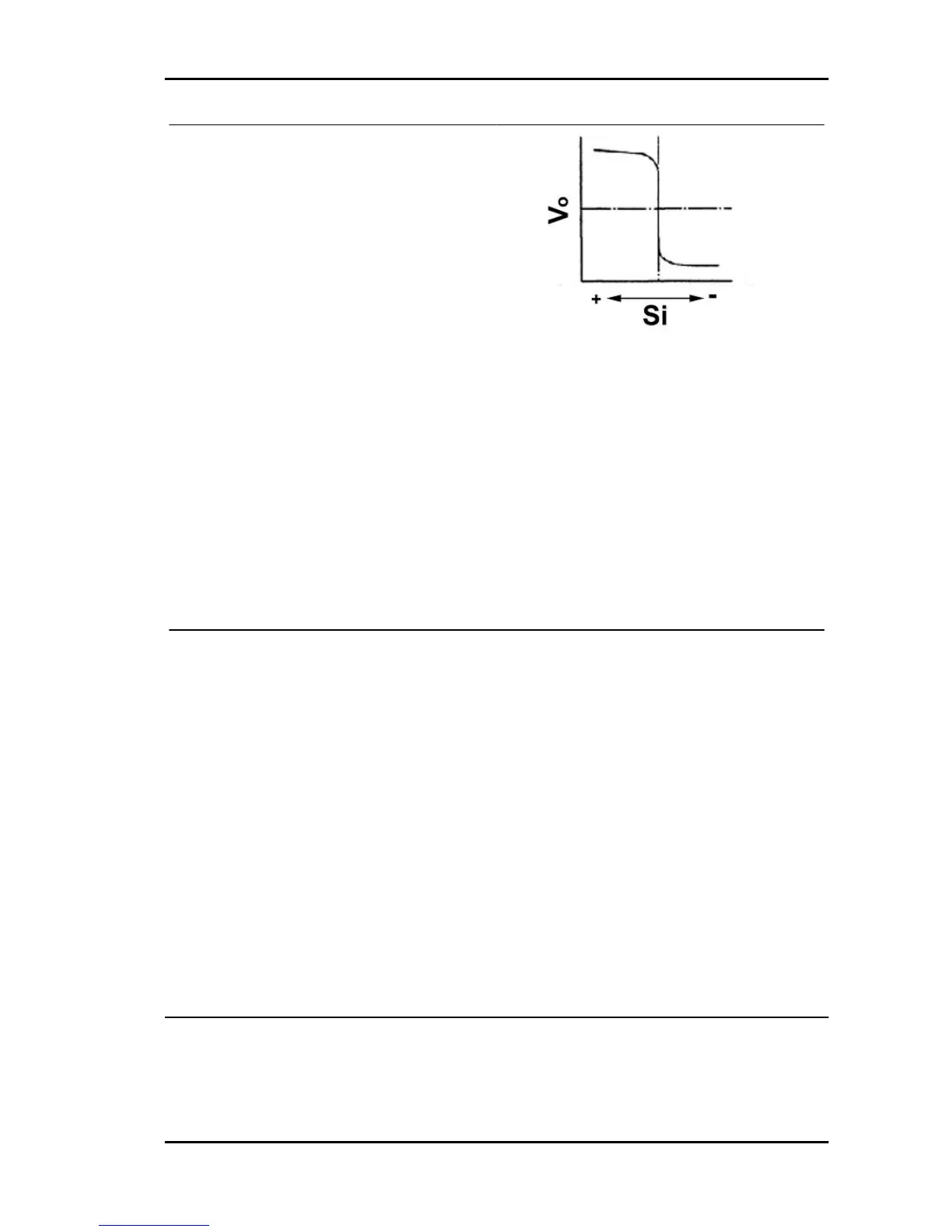
The front oxygen sensor (bank 1, sensor 1) detects
the concentration of oxygen in the exhaust fumes
according to the magnitude of the electromotive
force generated Vo. When the air-fuel ratio Si
turns richer than the stoichiometric ratio, a greater
electromotive force is applied to the electronic con-
trol unit (about 1 volt). Vice versa, when the ratio
turns leaner than the stoichiometric ratio, a smaller
electromotive force is applied to the electronic con-
trol unit (about O volt). In this way, the electronic
control unit determines if the air-fuel ratio Si is rich
or lean. The injection time is checked according to
this assessment.
KEY:
Si Air-fuel ratio
Vo Increasing voltage
Failure code Diagnostic failure code detection
Conditions
Affected area
P0130 If the following conditions (a) and (b) continue
to be detected after a certain period:
a) after warming up the engine, the signal ar-
riving from the oxygen sensor remains con-
stantly in the non-rich status, without turning
rich not even once.
b) The oxygen sensor output voltage remains
at 0.3 V or more, or at 0.6 V or less while run-
ning at idle speed after the engine has been
warmed up (detection logic with 2 interven-
tions).
- Air intake system
- Fuel pressure
- Injector injection
- Open circuit or short circuit in the heated oxy-
gen sensor circuit
- Oxygen sensor heated
- Engine electronic control unit
By using the diagnostic tester DS-21 or the OBD II general scanning device, confirm that the oxygen
sensor output voltage (bank 1, sensor 1) is equal to 0.1V or less. It is very probable that the oxygen
sensor circuit (bank 1, sensor 1) is open or short-circuited.
Functional check
1. With the ignition switch set to OFF, connect the diagnostic tester DS-21 to the Data Link Connector
through the special tool. Set the ignition switch and the tester main switch to ON. Set the tester to
"Continuous monitoring results" of the CARB mode.
PORTER 1.3 16V Iniection System
IS - 467

 Loading...