Checking for short circuits in the cable harness or
inside the ECU (2).
1. Set the tester switch and the ignition switch to
OFF. 2. Disconnect connector "B" of the special
tool from the ECU. 3. Set the ignition switch and
the tester switch to ON. Read the intake air tem-
perature value on the diagnostic tester.
Is the value measured about -30°C?
If SO: repair and replace the cable harness or the
connector.
If NOT: check and replace the ECU. (see the rel-
evant section EF-36)
NOTE: This diagnosis procedure generates fur-
ther temporary diagnostic failure codes, for exam-
ple P0105, and P0115, which can be cleared from
the memory at the end of the diagnosis.
KEY:1. EFI ECU control unit 2. Connector B 3. Cable harness side 4. Special tool (SST)
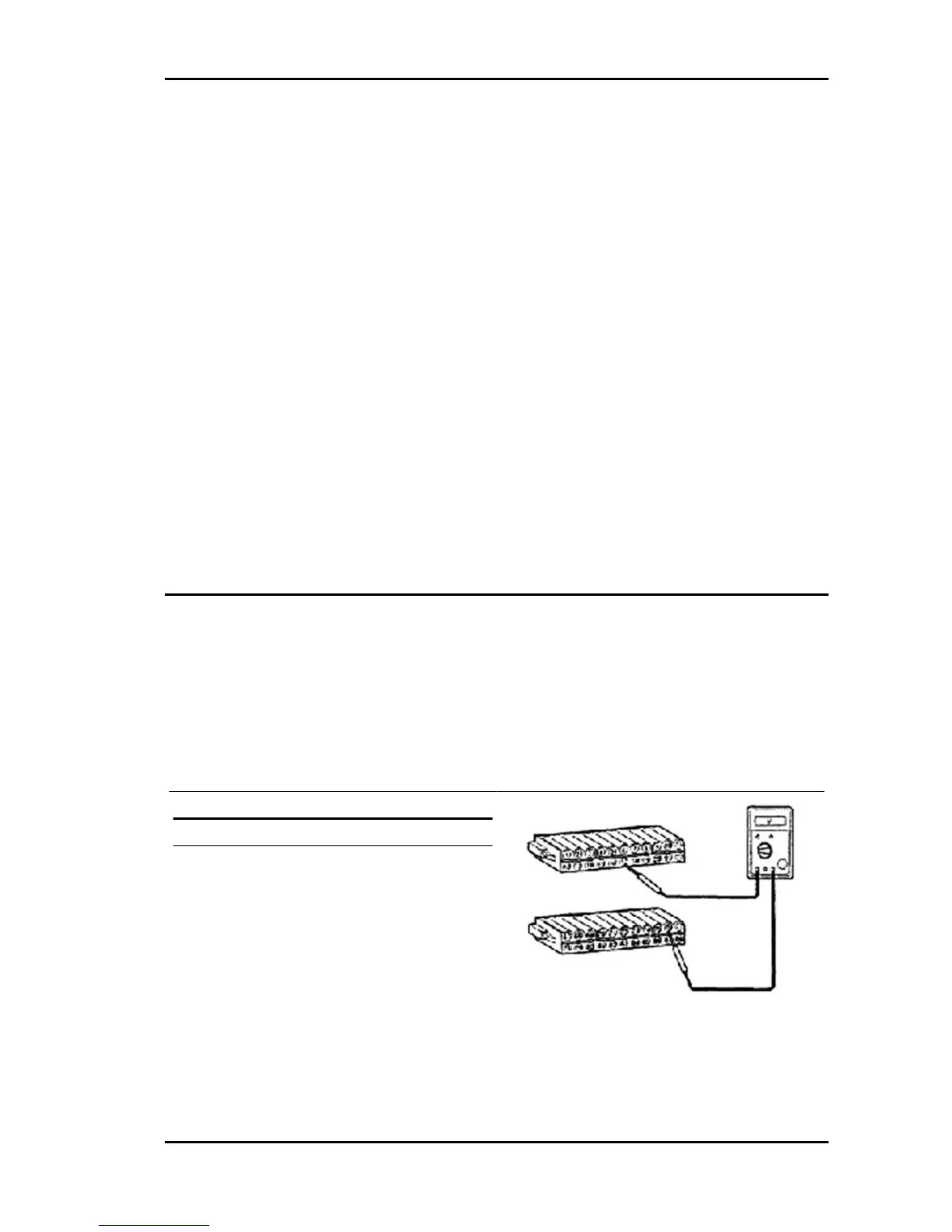
DIAGNOSIS WITH MULTIMETER AND INTERFACE WIRING.
Step 1
Checking the THA signal entering the ECU.
1. Connect the interface wiring. (See the relevant section "Connection of the special tool, Interface
wiring").
2. With the ignition switch set to ON, measure voltage between connectors (76) and (17) (THA-E2)
according to the following conditions:
Intake air temperature Specified value
20° C 1.8 - 2.9 V
60° C 0.6 - 1.2 V
PORTER 1.3 16V Iniection System
IS - 449

 Loading...