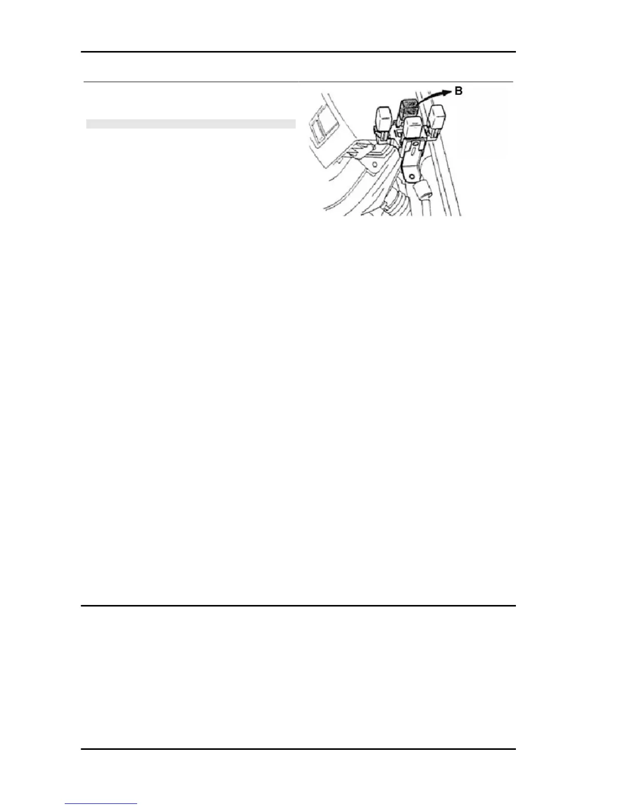
7. Fit the upper and lower covers of the steering
column.
N.B.
- IF THE DIAGNOSTIC TESTER DS - 21 IS USED, SELECT
" FUEL PUMP LOCKED" IN THE " ACTUATOR CONTROL"
WHILE THE ENGINE IS RUNNING, AND CONTINUE RUN-
NING THE ENGINE UNTIL THIS LOCKS.
Fuel leak check
After repairing the supply system, carry out the following checks to verify there are no fuel leaks.
1. Set the ignition switch to ON for three seconds, then put it back to OFF. Repeat the operation three
or four times.
2. Now, check there are no leaks in the supply system.
Troubleshooting safety measures
1. Never disconnect the connector from the electronic control unit, the battery cable, the ground lead
of the electronic control unit from the engine, or the main fuse, before the diagnosis information stored
in the memory of the electronic control unit is confirmed.
2. The diagnosis information stored in the memory of the electronic control unit can be cleared with the
diagnostic tester DS-21 or OBD-II general scanning device in the same way control is. Therefore, before
using the tester, read the relevant user manual so as to understand the operation perfectly.
3. Troubleshooting priority. A priority is specified for troubleshooting a certain number of diagnosis
codes in the relevant operation diagram, act observing such priority. If it is not specified, comply with
the priority indicated below and carry out troubleshooting for each code.
•
failure code different from P0171, P0172 (too lean/too rich in the supply system), and P0300,
P0301-P0304, P0314 (irregular ignition).
•
P0171, P0172 (too lean/too rich in the supply system).
•
P0300, P0301-P0304, P0314 (irregular ignition).
4. Before carrying out checks, read the section "system circuit checking safety measures" carefully.
Carry out the diagnosis being extremely careful where necessary.
Diagnosi del motore
General information
The engine and the engine control system of this vehicle are controlled by the electronic control system.
Besides, the vehicle is also equipped with an on board diagnosis system. If failures are detected in the
input/output systems (sensors, actuators, cable harnesses, connectors, etc.) of the engine control sys-
tem, the electronic control unit stores the relevant failure and informs the rider with the relevant
malfunction indicator light turning on or flashing (MIL, warning light). Besides, the operator is informed
Iniection System PORTER 1.3 16V
IS - 400
 Loading...