5 Motor control (MCTRL)
5.4 V/f characteristic control (VFCplus)
166
Lenze · 8400 HighLine · Reference manual · DMS 12.0 EN · 06/2017 · TD23
_ _ _ _ _ _ _ _ _ _ _ _ _ _ _ _ _ _ _ _ _ _ _ _ _ _ _ _ _ _ _ _ _ _ _ _ _ _ _ _ _ _ _ _ _ _ _ _ _ _ _ _ _ _ _ _ _ _ _ _ _ _ _ _
5.4.3.2 Adapting the Vmin boost
The V
min
boost (C00016) of the motor voltage serves to select a load independent magnetising
current which is required for asynchronous motors. The torque behaviour of the motor can be
optimised by adapting the setting in C00016
.
The nBoost_a process signal at the SB LS_MotorInterface
serves to carry out a V
min
boost as well:
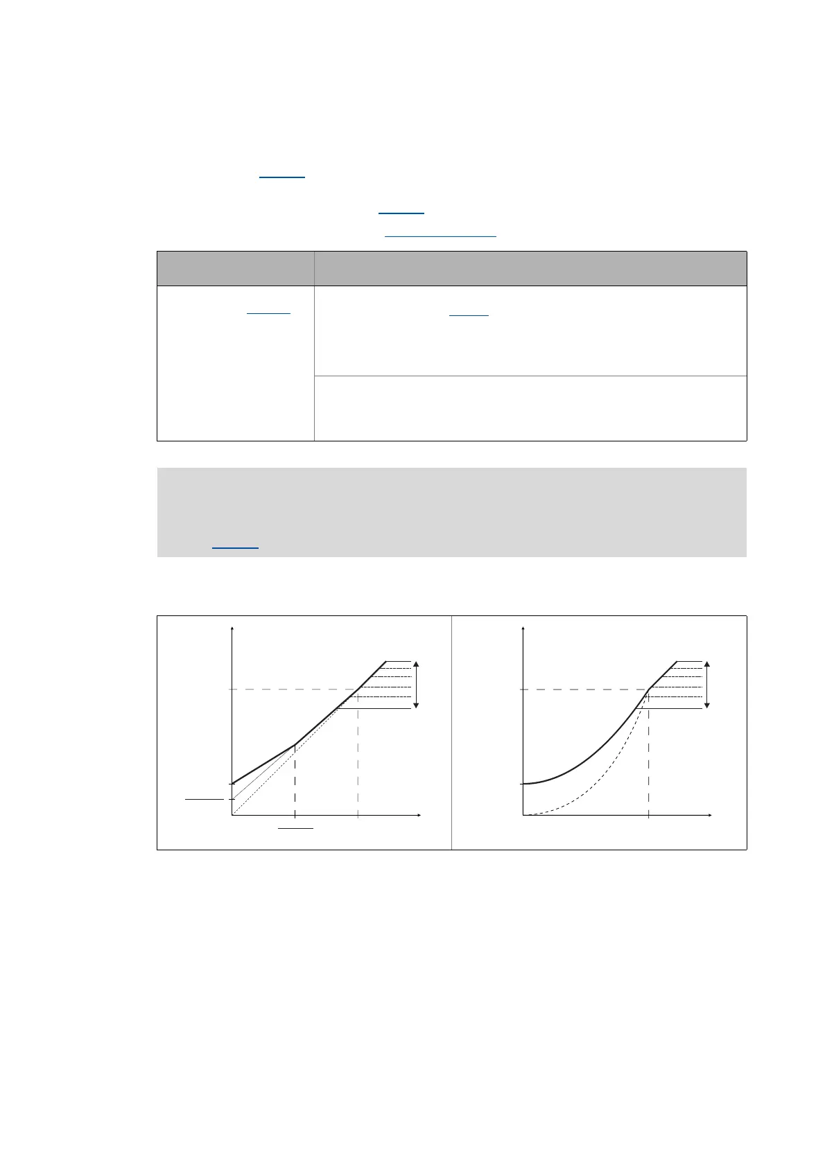
The general linear and quadratic V/f characteristics are shown in the illustrations below. The
illustrations show the impacts of the parameters used to adapt the characteristic shape.
[5-5] Representation of the linear V/f characteristic (on the left) and quadratic V/f characteristic (on the right)
Designator
DIS code | data type
Information/possible settings
nBoost_a
C00830/26 | INT
Process signal for the V
min
boost
• This signal is added to C00016
and has thus an increasing or decreasing effect.
• This signal serves to implement a load-dependent V
min
boost to improve the
torque behaviour in different load states, as for instance in case of operation in
generator or motor mode.
• Scaling: 16384 ≡ 100 % rated device voltage V
FU
(400 V or 230 V)
Stop!
Values selected too high may cause the motor to heat up due to the resulting
current!
Note!
The V
min
boost has an effect on output frequencies below the V/f base frequency
(C00015
).
C00015
C00016
C00015
2
C00016
2
V [V]
out
f [Hz]
V
(100 %)
rmot
1/N/PE AC 264 V
3/PE AC 264 V
3/PE AC 550 V
1/N/PE AC 180V
3/PE AC 100 V
3/PE AC 320 V
C00015
C00016
V [V]
out
f [Hz]
V
(100 %)
rmot
1/N/PE AC 264 V
3/PE AC 264 V
3/PE AC 550 V
1/N/PE AC 180V
3/PE AC 100 V
3/PE AC 320 V

 Loading...


