Lenze · 8400 HighLine · Reference manual · DMS 12.0 EN · 06/2017 · TD23 617
8 Basic drive functions (MCK)
8.12 Holding brake control
_ _ _ _ _ _ _ _ _ _ _ _ _ _ _ _ _ _ _ _ _ _ _ _ _ _ _ _ _ _ _ _ _ _ _ _ _ _ _ _ _ _ _ _ _ _ _ _ _ _ _ _ _ _ _ _ _ _ _ _ _ _ _ _
8.12.3 Process when brake is released
1. The controller inhibit is deactivated.
2. The magnetic field required for the holding torque is created in the motor (is already available
when a synchronous machine is used).
3. The bMBrakeReleaseOut trigger signal for holding brake switching element is set to TRUE for
releasing the brake.
4. After the brake opening time has elapsed:
•The bMBrakeReleased status signal ("brake released") is set to TRUE.
•In the "Speed follower
" operating mode, the drive synchronises to the already accelerated
speed setpoint.
• In the operating modes with setpoint request via control signal (operating modes "Homing
",
"Manual jog
" and "Positioning"), the ramping process starts after the brake release at 0.
5. After the waiting time set in C02589/3
has additionally expired, the status monitoring starts
again (if activated via bit 5 in C02582
).
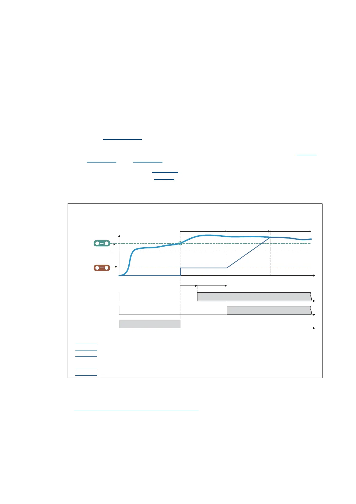
Time diagram
[8-41] Release holding brake in automatic mode via speed threshold
Related topics:
Feedforward control of the motor before release
( 621)
Feedforward control
Setpoint synchronisation
Follow setpoint
C02581/1
: Switching threshold
C02581/2
: Hysteresis for release
C02581/3
: Hysteresis for application
Time slot for feedforward control/magnetising
C02589/2
: Release time
C02610/1
: Ramp time for approaching the setpoint speed
bMBrakeReleaseOut
0
012
bMBrakeReleased
CINH
t
t
t
t
nSpeedSetValue_a
nSpeedSetValue_a_

 Loading...


